| Home | Accessory Kit | Marsh CD Collection | Library | Contact Us |
Chapter #1
What is a Rife Ray
tube and how does it work?
 |
Because some unknowledgeable people who profess to know a great deal about Dr. Rife's ray tube have claimed that it output harmful Microwaves we suggest that you also read chapter #4 of "The Rife Machine Report" along with this chapter in order to understand how Dr. Rife's ray tube never output any harmful Microwave frequencies. To read Chapter #4 clink on the link below.
Chapter #4: Are Dr. Rife's RF frequencies safe to use?
There are also some who claim that Dr. Rife's original machine used transducers or metal hand-cylinders and footplates. This type of machine was first built in 1957 by Dr. Rife's two business partners John Crane and John Marsh. It was never used by Dr. Rife. Below is a link to another page which clearly shows that Dr. Rife only used a plasma ray tube machine.
What method did Dr. Rife use: A ray tube or metal hand cylinders?
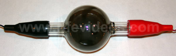
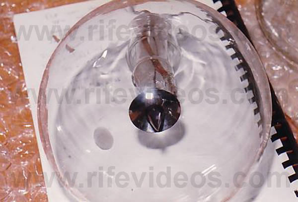
Dr. Rife used a ray tube with his Rife Machines. The photo, shown above, is a picture of the style of double-bubble ray tube which Dr. Rife used for many years in his laboratory. A ray tube was made out of glass, quartz or Pyrex and was filled with a noble gas or a mixture of noble gases.
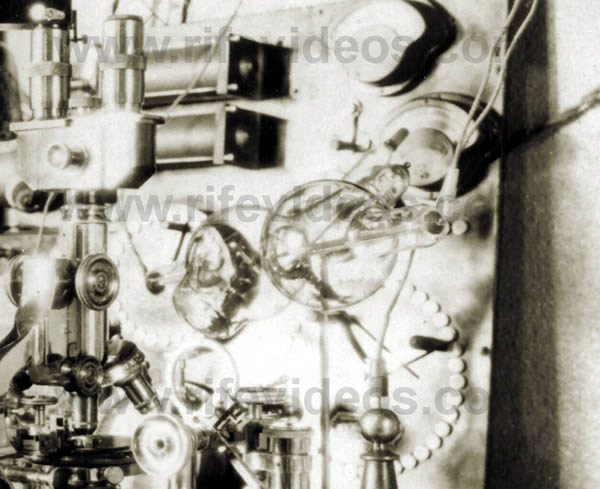
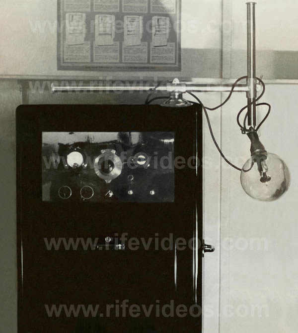
The next photo, shown below, shows Dr. Rife's double-bubble ray tube in his laboratory right next to his microscope. You will notice it looks almost exactly as the photo above.
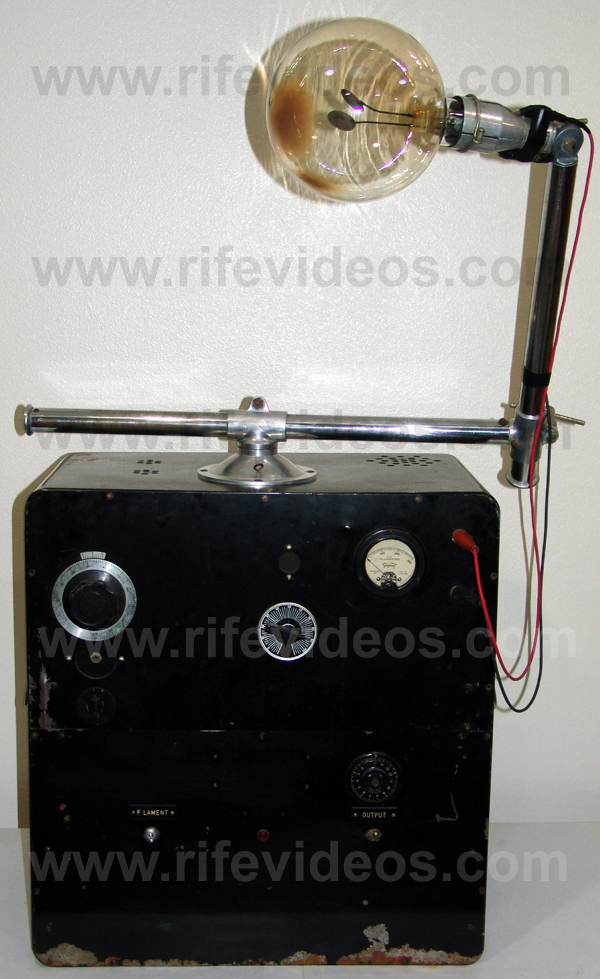
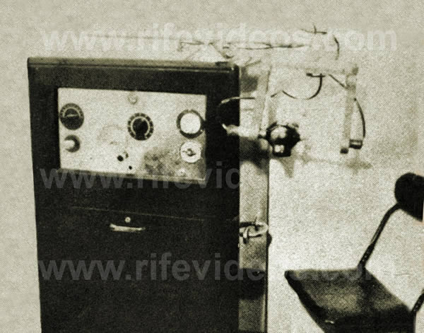
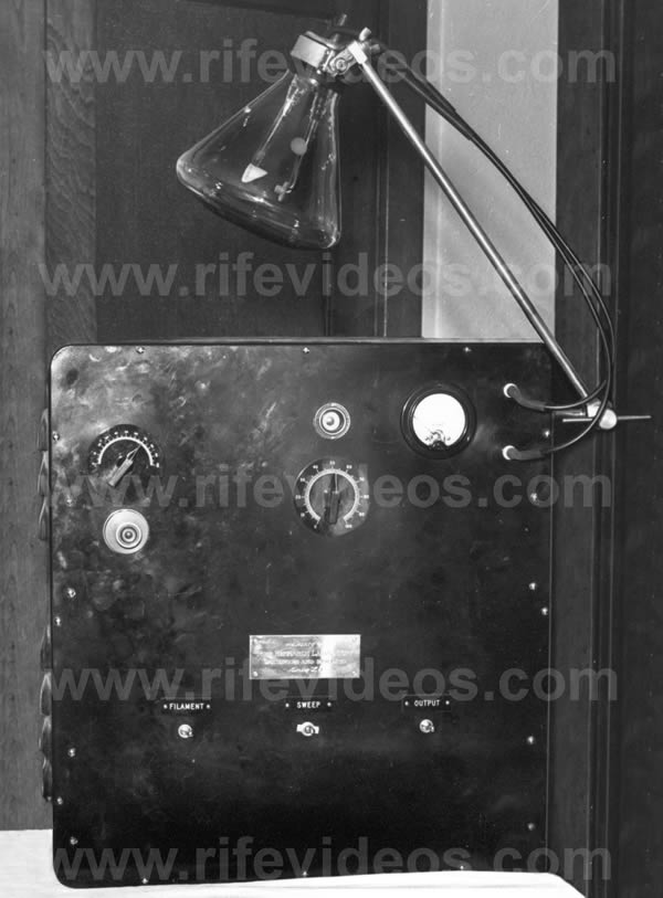
Below is a photo of the only known surviving "Original Rife Ray #5 or Beam Ray Clinical instrument." This 1938-39 original instrument was analyzed for this report.
Some people believe that there was something magical to the gas mixture that Dr. Rife used in his ray tube. There are also people who claim that their instrument which they sell uses some proprietary blend of gases which makes their ray tubes work exactly like Dr. Rife's. Others even claim that their gas formula works better than Dr. Rife's did. The truth is that none of this rings true because of what Dr. Rife said about this subject. Dr. Rife knew more about these gases than most anyone else since he used different gas mixtures over a thirty-year time span. The fact is Dr. Rife used many different mixtures of gases but eventually ended up using only helium. He stated:
RIFE: “We have experimented with various inert gases and we found that helium stood up by the bombardment better than any of the other gases. That’s why we use it. We don’t care about the color or anything of that sort. It stood up better over many more hours of bombardment than the argon and the crypton [krypton] and those different gases that we tried.” (John Marsh Collection, Gonin and Siner Papers, Page 25).
From what Dr. Rife said in the above quote it is apparent that he tested many different gases over the years in his laboratory and they all worked. But we find that he eventually decided to use only helium because it lasted longer in the ray tube.
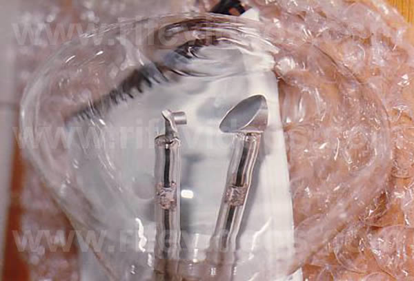
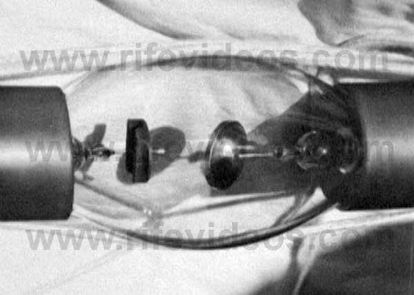
The ray tube was connected to Dr. Rife's Machine by two wires. These wires were connected to two round metal bars that went into the glass ray tube and they had round disks connected to their ends. One disk was straight and the other one was on a 45-degree angle. This gave it a directional effect on the patient.
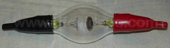
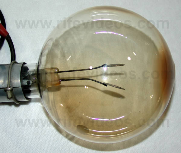
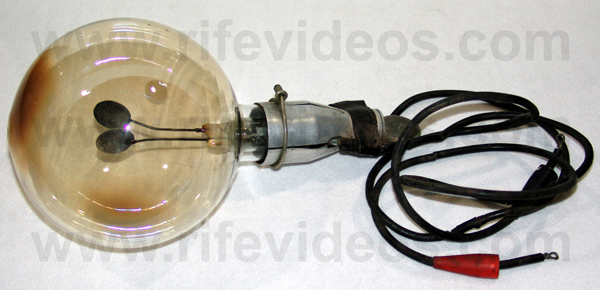
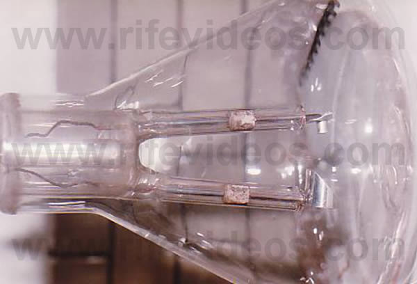
Below are two photos showing the internal electrodes that were built into the ray tube. You can see that one is straight and the other is on about a 45-degree angle. The first photo is of a ray tube built in the 1970s by John Marsh. The second photo is of the ray tube of the original Rife Ray #5 or Beam Ray Clinical Machine showed above.
Dr. Rife stated that the ray tube was “a partial directional antenna". Because the scientific technology behind ray tubes had already been perfected, Dr. Rife worked with that technology and only had to make some adjustments for it to work the way he wanted it to in his applications. Bertrand L. Comparet, Dr. Rife’s attorney, stated in an interview the following:
COMPARET: “Now, the original instrument had a tube, like an X-ray tube. That was the way in which Rife developed it. You see, all the X-ray work necessarily was done with a beam projected from a tube. So, Rife worked on the same basis.” (1970’s Bertrand Comparet Interview #32).
Although Dr. Rife used X-ray tubes in his work they did not put out any X-rays. Because the ray tubes used inert gases they did not produce X-rays. They work on the same principle as a neon sign. The gas that is used in a neon sign does not produce any harmful rays of any kind. Inert gases such as helium, argon, krypton, neon, and others can safely be used in these ray tubes. These gases are considered noble gases and there are 18 different types. The ray tube is just an antenna and the noble gas will emit the frequency when the plasma is lit. This makes a ray tube a safe method of delivering the frequencies. If you use a metal antenna with 50-watts and someone just happened to touch it they could receive severe third-degree RF (Radio Frequency) burns. In 1958 Dr. Rife, John Crane, and John Marsh had the ray tubes tested to verify that they did not output any harmful X-rays. Later in 1972, John Marsh had another test done. Click here to read the 1958 test document and Click here to read the 1972 document.
Many people believe that ray tubes are just as efficient as metal antennas, and this may be true. They also believe that the energy emitted from a ray tube will actually travel farther with less loss than a metal antenna. Since there are no actual scientific tests comparing the output of ray tubes to metal antennas it is hard to know for sure if these assumptions are correct. For this report, we will accept what is known, not what is unknown. Therefore we will compare ray tubes to metal antennas since they both are designed to emit frequencies.
There are limitations to metal antennas that need to be understood and this has to do with the laws of physics. It is referred to as the "Inverse-Square Law". This law deals with power loss and distance. We will give a simple explanation which should suffice since we are trying to stay in layman's terms and make it easy for the average person to understand this information. When a circuit is properly tuned metal antennas are very efficient. About 100% of the energy that you put into a metal antenna comes out, but only if the impedance is matched correctly.
Dr. Rife’s Rife Ray #3 instrument information which we obtained from the Rife documents lists that 50-watts RF was input into the ray tube. If we compare this to a metal antenna this means about 50-watts would have passed through and come out of the ray tube. When it comes to metal antennas and the “Inverse-Square-Law” on the signal loss this would mean that you would have to divide the 50-watts which comes out of the metal antenna by the distance squared for every foot that you move away from the antenna. In mathematics, a square is a result of multiplying a number by itself. The exact power loss of a ray tube, as stated before, is not known but if a ray tube is equally as effective as a metal antenna, and we believe it is, then the same laws of physics would also apply to it.
Because no actual scientific tests have been done with ray tubes demonstrating that they are exempt from the inverse-square law then we are left with only one conclusion, this law does apply to ray tubes. Because of this, we will use this inverse-square law of power loss for a ray tube. Therefore, with a 50-watt power output at one foot away (1 X 1 = 1. 50 ÷ 1 = 50) from the ray tube, you would have 50-watts. At two feet (2 X 2 = 4. 50 ÷ 4 = 12.5) you only have 12.5 watts and at 3 feet (3 X 3 = 9. 50 ÷ 9 = 5.5) you only have 5.5 watts. These laws of physics are important to understand because Dr. Rife and the doctors that used his equipment put the ray tube within a few inches to a few feet of the patient’s body for maximum power transfer. One of Dr. Rife's 1950's business partners, John Marsh, wrote a paper in which he stated that the Ray tube should be used from 12 to 24 inches from the body. Some other documents list 9 to 12 inches so there is some leeway:
MARSH: "A frequency instrument with therapeutic applications which has been developed and successfully tested over a period of year’s works on the principle of stimulating tissue with low energy, low frequency pulsating current. It applies electron transmission at variable frequencies from an applicator source, which consists of either (1) a bare anode and cathode (in direct contact with the body) and constructed from metal for easy transmission flow of electrons, or (2) from an antenna broadcast source [Ray Tube] at a distance of 12 to 24 inches." (An Explanation of the JLMSQ-1A frequency instrument and its use. Page 1 Page 2).
In another paper written in 1959 entitled "Electron Therapy" this same distance is mention twice. Dr. Couche said that he would sometimes touch the body of the patient in the area that needed to be treated. When we discussed this with Dr. Robert P. Stafford M.D.,he said that when he treated cancer patients he would put the ray tube within a few inches of the body and treat a 6-inch square area. He would move the ray tube up and down and back and forth so that the whole 6-inch area was treated. He said that he did this because of the way the phanotron (ray tube nickname) ray tube worked. The design of a phanotron ray tube makes it partially directional and concentrates its energy or power into a smaller area. Due to the "Inverse-Square Law" power loss, it is easy to understand why Dr. Stafford, Dr. Couche, Dr. Rife and the other doctors used the ray tube right next to the body. Many people have used these RF (Radio Frequency) ray tube instruments and have noticed that within several feet they will get a strong reaction but beyond this, it drops off very quickly. It is apparent that there was a good reason why the ray tube was used close to the patient's body.
From these statements, we have quoted it would appear that Dr. Rife’s ray tube instruments had a very limited range, but this assumption would be incorrect. The next quotes will clearly show that Dr. Rife’s 75-watts 1936/1939 #5 instrument had a large effective range beyond a 30-foot radius. This quote is taken from the “Electro-Magnetic Force Field Treatments” document clearly states that the control rats, those rats they injected with the organism but did not want to be treated, needed to be kept at least 80-feet away from the plasma tube. We quote:
NOTE: “Be sure to isolate the rats that were injected from all of those being treated as these Radio Waves can travel a distance from the area of treatment. I'd suggest no less than 80 feet or more from the rest being treated. The rats that are injected for control purposes should not come in contact with the treatments given to the other groups, for safety purposes in testing. Much care in this area [should] be given.” “Electro-Magnetic Force Field Treatments”
http://www.rifevideos.com/instructions_for_the_use_of_the_rife
frequency instruments.html
This “no less than 80-feet or more” quote shows the plasma tube output had a large radius range. If a 30-foot radius was not possible then why did they so strongly emphasize the 80-feet distance of separation that needed to be used during the tests? The 1936/1939 #5 instrument was only a 75-watt output machine using an RF carrier frequency in the 3 Megahertz range. It is clear that it had more than a 30-foot radius range. It is also apparent that the greater the power the greater the range. This next quote from Dr. Milbank Johnson M.D. is from a letter he wrote in November of 1936 when they were testing the 75-watts 1936/1939 #5 instrument. As you read this quote you will notice that Dr. Johnson’s laboratory probably had several rooms so it was not a small building and could have easily been 60 feet to 80-feet long. But even if it was only 40 or 50-feet long this would still be more than a 30-foot radius. We quote:
DR. JOHNSON: “Last summer, in hunting for the M.O.R. for the other two reproductive forms of the cryptomyces pleomorphia, we ran into a new band of oscillations which introduced itself to us by killing all three forms - those that we called BX, our filter-passing form; then a transitional form such as you found in the monocytes in the blood; and then the third or highly developed form coming from the sporangius forming from the hyphas of the mycelium. At the same time that this new wave band arrived, we broke all the glass in the laboratory of a certain shape, not only in the room where we were working but in all the other rooms...we had been troubled a great deal with a mold because in the microscope room there were no windows, but this band not only destroyed that mold, which was growing on the leather objects in the room, but every bacteriological culture that we had in the laboratory! It cleaned us out completely so we had to start from scratch and replace our losses. In fact, we were all so surprised that we began to feel each other’s pulses to see if we were still alive. As no harm had been done to us, we proceeded to test the new band [harmonic sidebands method] out on mice, rats, rabbits, guinea pigs and dogs. So far as we were able to discover, it is not at all destructive or injurious to normal cell tissue. While we have been forced to modify our machine so as to produce this new band, still it is so much more effective clinically that we look upon it as a very advantageous discovery. However, our experience has forced us to do all of our experimenting with the new ray [1936/1939 #5 or Beam Ray Clinical instrument] completely outside of our laboratory building or abandon all form of bacteriological experiments, because it instantly kills them all.” (Letter from Dr. Johnson to Dr. Gruner (copy sent to Dr. Rife) dated, November 4, 1936. Page 1, Page 2).
http://www.rifevideos.com/chapter_9_1938_to_1939_beam_ray
corporation clinical_rife_machine.htmlIt is obvious from this quote that the 75-watt output from the plasma tube of the 1936/1939 #5 machine was not limited to a 10 inch to 2 feet distance. For it to have been capable of doing what Dr. Milbank Johnson M.D., described it had to have had a greater range than just a 30-foot radius. It is apparent that the 80-foot distance or radius was necessary because they had to move all of their animal tests outside of the lab. This was all done with just a 75-watt ray tube machine with an RF carrier frequency in the 3 Megahertz range. If an instrument has a 100 to 200-watt power output then the distance would be greater according to the instrument's power output. From these quoted statements we find that the ray tube was used close to the animals and patients for the greatest power transfer, but it also had a much greater range than just a 30-foot radius
Some people do not understand that all of Dr. Rife’s ray tube instruments of at least 50 to 75-watts output, had this 30-foot or larger radius range. Because they do not understand this fact they promote the concept of “Resonant Capacitive Coupling” and the use of a 20 Megahertz or higher RF carrier frequency for their instruments 30-foot plasma tube radius range. They also claim that no other instruments with lower RF carrier frequencies, such as the 3 Megahertz frequency range, used in the 1936/1939 Rife Ray #5 had this radius range. Both the 80-feet quote and Dr. Milbank Johnson’s quote clearly show that the 1930’s/1950’s instruments had this 30-foot radius range even with a 3 Megahertz carrier frequency. It is apparent that all RF carrier plasma tube instruments with 50 to 75-watts of power output have this same capability regardless of the RF carrier frequency range used. If "Resonant Capacitive Coupling" is actually part of the equation of how a plasma tube works then these quotes prove it is not limited to the 20 Megahertz carrier frequency range.
What is also very interesting is people who promote “Resonant Capacitive Coupling” also claim that their instruments are not governed by the “Inverse Square Law.” There is no scientific evidence backing this claim. Regardless of what anyone may claim all ray tube instruments are governed by the “Inverse Square Law” of physics. This 30-foot radius range capability is not based on a higher RF carrier frequency but it is a natural RF (Radio Frequency) plasma tube function based on the power output of the instrument. What “Resonant Capacitive Coupling” mostly deals with is short distance wireless power transfer like that used with wireless cell phone chargers. Here are two links to videos about this subject the reader may want to watch. The possibilities of that technology will make many things possible in the near future.
https://www.youtube.com/watch?v=-Wf7aadxBkE
https://www.youtube.com/watch?v=Gw6XtzEOlyIAnyone who is willing to do some reading will find proof that the human body resonance is far more complex than what most people understand. “Resonant Capacitive Coupling” is not capable of resonating with the whole body. This next quote is taken from the “Scientific Report of the Harvard Education Courses of 1997” gives more understanding about how RF frequencies interact with human tissue. It clearly explains how complex the human body is and how it is impossible for the body to have a single resonant frequency. We recommend that you read this entire report:
REPORT: “How does RF radiation interact with human tissue? A radio wave in space is characterized by its frequency, intensity of electric and magnetic fields, direction, and polarization. The interaction of external radio waves with biological bodies produces internal electric and magnetic fields, which can be calculated by solving Maxwell's equations for the given boundary conditions. This becomes a complex problem, however, because biological bodies are heterogeneous and complex in shape, making an exact solution impossible. In addition, the intensity of the internal field is greatly dependent on the boundary conditions under which the external field is applied. The frequency, intensity, and polarization of the field, in addition to the size, shape, dielectric properties of the exposed body, the spatial configuration of the exposure source and the body, and the presence of other objects in the vicinity, play a big role in the effect the radio waves will have on the body. For this reason, the internal field created in a mouse under a given external field will be much different than the internal field created in a man under the same external field. Exact field strength is dependent on local geometry: in a man standing in a field perpendicular to the ground, the average current density in the legs is greater than in the trunk, by a factor that corresponds to the ratio of the cross-sectional areas of the trunk and leg. Absorbed energy depends on the size of the body, curvature of its surface, ratio of body size to wavelength, and the source characteristics. The frequency of maximal absorption is called the resonance frequency (for humans it is between 70 and 100 MHz), and depends on orientation with respect to the incident field. In general, the rule is that the shorter the subject, the higher the resonance frequency, and vice versa."
http://www.rifevideos.com/absorption_of_rf_radiation.htmlThis report explains how complex body resonance really is. The body’s dielectric properties, frequency, intensity, and polarization of the field including size, shape, length, trunk, legs, curvature, standing, sitting or laying down making it impossible to have a specific resonant frequency because biological bodies are heterogeneous and are very complex in shape. This report points out that even objects in a room will have an effect. For all of these reasons, no human body could ever have a specific resonant frequency and this is why they give a range of 70 to 100 Megahertz. These claims of “Resonant Capacitive Coupling” are scientifically un-provable and incorrect. Power output determines distance.
Now we will again discuss the ray tube. We built both the Aubrey Scoon Beam Ray #5 instrument and the 1953 AZ-58 Beam Ray #5 replica ray tube Rife Machine. The 1953 AZ-58 (Rife instrument made by Life Labs) was built from schematics that are on Stan Truman’s site, http://www.rife.org, under AZ-58 research information. This AZ-58 instrument is nearly the same as the original Rife Ray #5 or Beam Ray Clinical instrument and schematics can be found on this page.
Both Aubrey Scoon’s instrument and the original Beam Ray instrument use sine wave audio frequencies and the 1953 AZ-58 uses square wave audio frequencies. John Crane listed the AZ-58 as outputting only 14-watts but this was not correct. We tested it and found it outputs about 50-watts. The 1950's Aubrey Scoon instrument outputs about 50-watts also but the original 1936/1939 Rife Ray #5 output 75-watts.
We did some resonance tests using a crystal designed for testing resonance. The tests were done using the AZ-58 replica and the Aubrey Scoon replica Rife machine using a phanotron ray tube outputting 50-watts. The audio frequencies broadcast out of the ray tube would only resonate with the crystal in front of the ray tube. When we turned the ray tube more than 45-degrees, either to the right or the left, of the center of the ray tube we could not resonate the crystal. We also could not resonate the crystal at all on the backside of the phanotron ray tube proving what Dr. Rife said was correct:
RIFE: “The ray tube is a partially directional antenna.”
One interesting fact worth noting is the ray tubes that do not use the internal electrodes, like the Phanotron ray tube, have a higher field strength reading which indicates a greater output. These ray tubes use copper collars or wire wrapping around the ray tube. Ray tubes that use this method also last longer because the gas inside the ray tube does not get contaminated. The contamination comes from internal metal electrodes. Over time the metal from the internal electrodes comes off and slowly contaminates the gas. It will also deposit on the inside of the glass making the ray tube go dark.
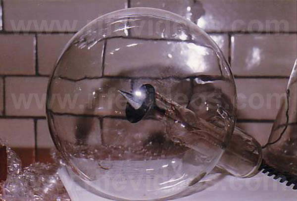
In the next two photos, shown below, you can see how the ray tubes have darkened. The main reason Dr. Rife used the helium gas was due to the fact that it took longer for this darkening to take place. But no matter what gas was used the ray tubes would eventually darken. Today with the ray tubes that do not have the internal electrodes we can use any of the noble gases (Helium, Argon, Neon, etc.) that Dr. Rife used without worrying about any contamination. These ray tubes can last for more than 10 to 15 years without ever needing to be re-gassed.
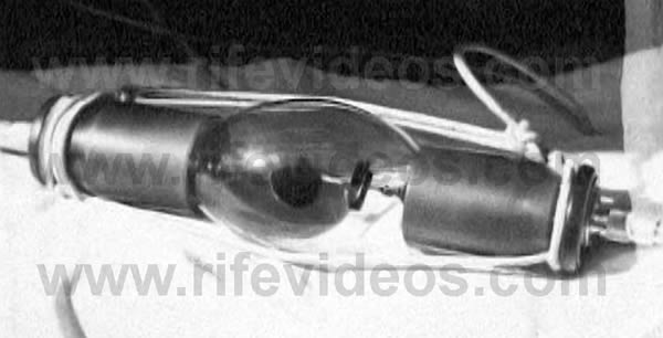
The next photo, shown below, is a picture of Dr. James B. Couche's Rife Ray #5 or Beam Ray Clinical instrument which he purchased from the original 1938-39 Beam Ray Corporation. The ray tube is Dr. Rife's original double-bubble ray tube which he used for over 30 years in his laboratory. You can see how the ray tube has darkened. This was a common problem that required the ray tubes to be cleaned and re-gassed on a regular basis. A better view of this double-bubble ray tube is the first photo shown at the top of this page.
The next photo, shown below, is also of a Beam Ray Clinical instrument. If you look at the ray tube you will see that it has a different style of the electrode.
In the next two photos, shown below, you can see a better view of the ray tube found in the photo above.
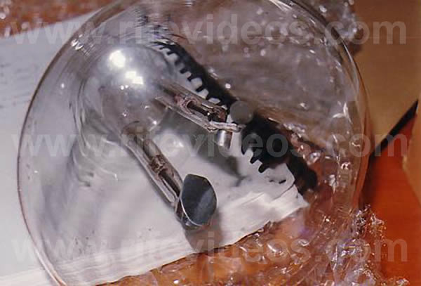
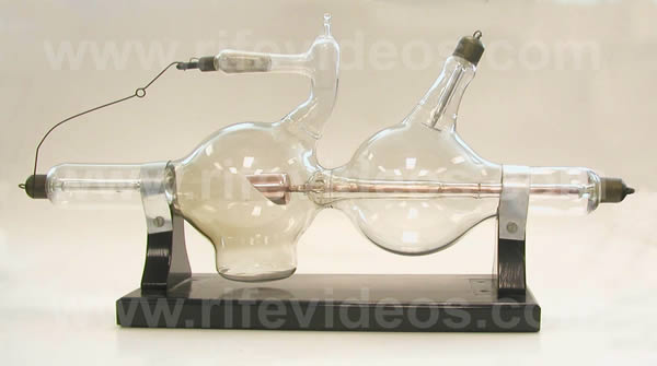
In the next photo, shown below, is an original Rife Ray #5 or Beam Ray Clinical Machine built by Philip Hoyland in 1938. This instrument has a different style of ray tube than the others we have shown. Dr. Rife said that they stopped building this style because the bottom of the ray tube kept falling off. He said the sharp curve would get stressed and crack causing it to fail.
The next three photos, shown below, are close up photos of this same ray tube shown in the above photo.
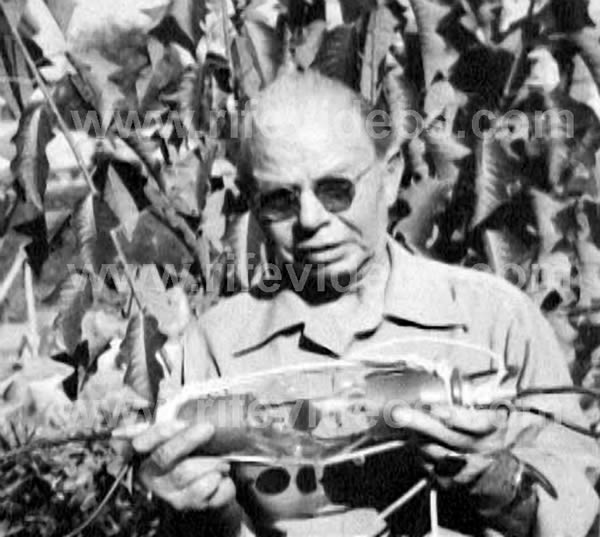
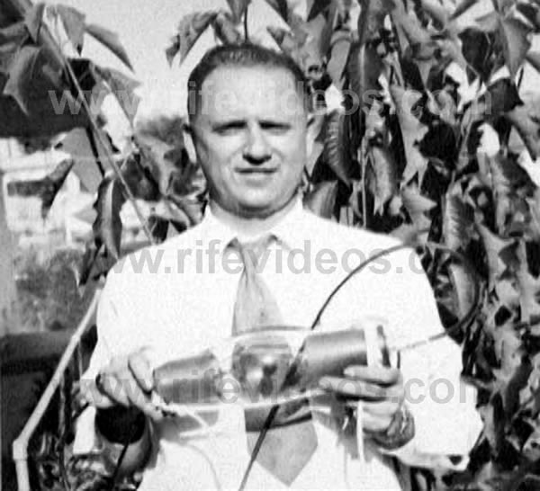
Below are four photos of a different style of ray tube. The first photo shows Dr. Rife holding a ray tube. The second photo shows John Crane holding the same ray tube. The third and fourth photos are a closer look at this ray tube. These photos are from the early 1950s.
Chapter Summary: A ray tube is a plasma antenna built for the purpose of outputting frequencies. Dr. Rife built many different styles of ray tubes. The gas used inside the ray tube does not really matter as long as it is a noble gas (Helium, Argon, Krypton, Neon, etc.). Dr. Rife settled on using helium because it lasted longer in a ray tube that uses internal electrodes. The ray tube made it possible for Dr. Rife to safely use a powerful RF (Radio Frequency) frequency instrument next to a person or microscope. Dr. Rife preferred using a ray tube over pad type instruments because a great deal more power meant a better outcome for the patient.
To fully understand how a ray tube works this chapter should be read in conjunction with Chapter 2, Chapter 4, Chapter 17 and Chapter 18.