| Home | Accessory Kit | Marsh CD Collection | Library | Contact Us |
Aubrey Scoon's
1939 Rife Beam Ray
1) Used a Ray Tube.
2) Used a fixed 3.30 MHz carrier frequency.
3) Modulated sine wave audio frequencies onto a sine wave carrier frequency.
4) Power usage was about 460 watts. Output to the ray tube about 40 watts.The 1939 Beam Ray Machine?
After you have read this information about Aubrey Scoon's instrument you will want to read Chapter 11 of The Rife Machine Report which gives more information about this instrument.
Aubrey Scoon’s instrument is an important part of this report. We felt that his information about this machine should be included . All of this information was originally on Aubrey Scoon’s web site but since he has passed away his website is no longer available. This information is to important to be lost. Even though we now know that his machine was not built by the original Beam Ray Corporation it is still a copy of the original Rife Ray #5 or Beam Ray Clinical instrument. This machine was built by Verne Thompson in 1952 or later and used the original 3.30 MHz RF carrier frequency. It also used Philip Hoyland’s original audio frequencies that will produce the original sideband frequencies that will would hit the higher harmonic frequencies of Dr. Rife’s original M.O.R.s.
Below is Aubrey Scoon's written Report:
In 1938, a group of British researchers headed by Dr Bertram Winter Gonin, sought to buy some experimental machines from Rife to confirm his work. At that time, Rife had no commercial operation capable of handling the orders and at the instigation of his old friend Ben Cullen, Rife consented to the formation of a commercial company called Beam Rays Inc. At that time, the majority owner of the rights to the machine was an electronics engineer called Philip Hoyland. Hoyland had designed and developed all of the original Rife machines since late 1934. Hoyland and Rife became partners in Beam Rays Inc. The company produced a small number of machines but suffered internal conflicts because of the actions of some of the other partners and because of frictions between Hoyland and Gonin's group. Hoyland believed that Gonin and his partners were trying to steal the technology for themselves. Subsequently, the company was destroyed in 1939/1940 when Hoyland brought a lawsuit against Beam Rays in an attempt to stop one of the partners from illegal stock trading and also to dissolve the contract with the British. Fuller details of this are being written up and will be posted here in the near future.
The Beam Ray Corporation produced a number of machines. I'm not sure of the exact number as I have seen varying accounts, but I believe that about 17 machines were produced and shipped to MD's in California. Another four machines were shipped to England to Dr. B. Winter Gonin of the London School of Tropical Medicine. There was some argument between Rife and Hoyland over these machines and their operating principle, however various MD's including James Couche used one of these machines for many allegedly successful treatments of patients for many years.
The U.K. Rife Research Group managed to get access to one of the machines believed to be one of the originals that were shipped to California in the late 1930's. I reverse engineered that machine and present the results below. I have a lot of data on this machine of which this is only part, I will add things as I get time as much of the data needs to be organized properly. The exact date of the machine is unknown - we know that it was built sometime between the autumn of 1938 and the early part of 1939 - so it may actually be a 1938 machine.
I would like to express my thanks to Robert Harrison, an expert valve/tube engineer (I'm not a valve/tube expert) who gave me massive help and support during the reverse engineering process and who corrected numerous silly mistakes that I made! My thanks also to Stuart Andrews and Bob Haining for their help and support in this effort.Below are the machine schematics and links to some photographs. The schematics have been rendered into PDF format which allows them to be zoomed to resolve fine detail.
WARNING: These schematics are presented for information only. Do not try to construct a copy of this machine unless you are knowledgeable and experienced in high voltage valve/tube work. The tube filaments need to be heated for a couple of minutes before switching on the HT - failure to do this will blow them. In addition, some parts of this circuit use up to 1750 volts DC at substantial current and can easily kill in inexperienced hands.
Output Stage Schematic
Complete Schematic
Original Plasma Tube Schematic
Booster Amplifier Schematic
Below is a third schematic. This is for a transistor booster amplifier I designed. It is possible to separate the Beam Ray machine output stage from the oscillator stage and to drive the output stage directly from a modern digital frequency generator. This allows much more precise and accurate frequency control than the original. But the output stage requires over 40 V p-p to drive it properly at 100% modulation and most modern generators are not capable of outputting this kind of voltage. So the booster stage allows a low level signal between 20Hz and 200Khz (the original range of the machine) to drive the output at up to approx 66 V p-p without significant signal distortion (it can be driven at higher inputs of up to 2 V p-p with clipping). An input of 951 mV will cause 100% modulation of the Beam Rays machine and an input of 1.5 V p-p will result in significant over modulation without distortion of the modulating signal itself. The booster amplifier has a bandwidth of approximately 800 KHz and so can also be used as a general purpose wideband, high voltage buffer amplifier as well.
Booster Schematic
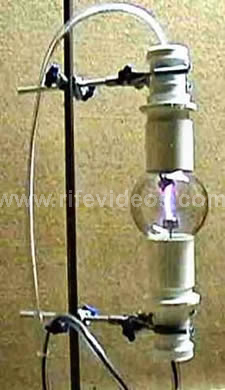
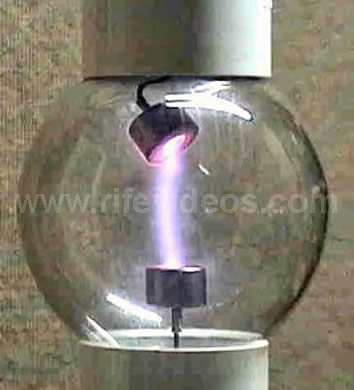
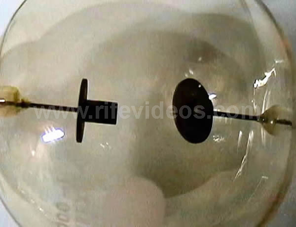
Plasma Tube Photos
The photographs below show two views of the Nazarov phanotron running on the Beam Ray Machine.
And here in the photo above is a close-up of the electrodes of the original plasma tube.
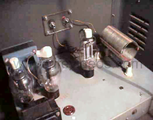
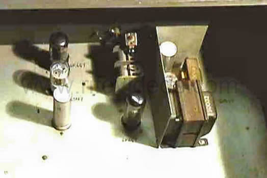
Inside the Beam Rays Machine
The picture above is of the output stage of the machine. The tank coil can be clearly seen on the right with the 812 (should be 809) output triode next to it. The output jacks are in the center top. The HT transformer is at the back left with the two 866 mercury vapour rectifiers in front of it. Picture courtesy of Stuart Andrews.
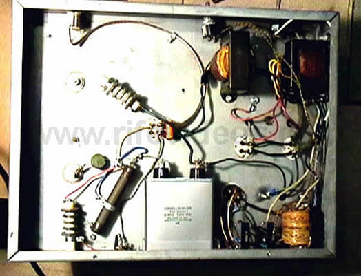
The next photo above is the underside of the output stage (note that some components on both stages had to be replaced with modern ones to get the machine working because the originals had deteriorated too much).
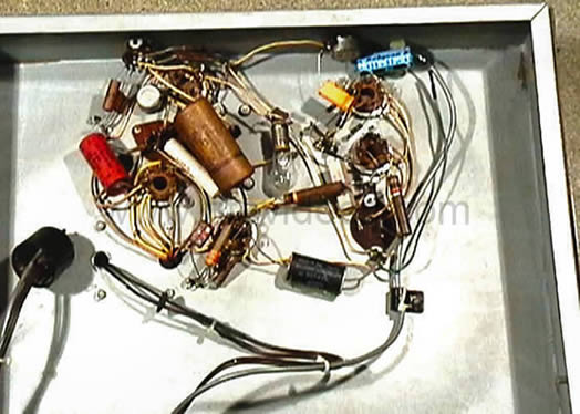
And this photo above is a of the underside of the oscillator stage.
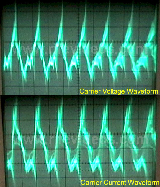
Beam Ray Carrier Waveform Photographs
Here are various photographs I took of the machine's waveforms on an oscilloscope. Note: these were taken with the 812A tube in place. The waveforms produced when an 809 is used are smoother and more sinusoidal.
These are the carrier waveforms for both voltage and current. The actual carrier frequency of the machine depends very much on the plasma tube and also on coupling effects between the tube and any person in the vicinity.
This has made it very difficult to get accurate measurements of the machine because even being in the same room as the machine causes the frequency to alter!
However, after many experiments I am reasonably certain that the resting carrier wave frequency, undisturbed by any local effects is approximately 3.33 MHz.
Because the wave is not a pure sine there are strong harmonics at many other frequencies as well. Some of the dominant harmonics have been observed at approximately 2.3 MHz, 4.6 MHz and 9.09 MHz.
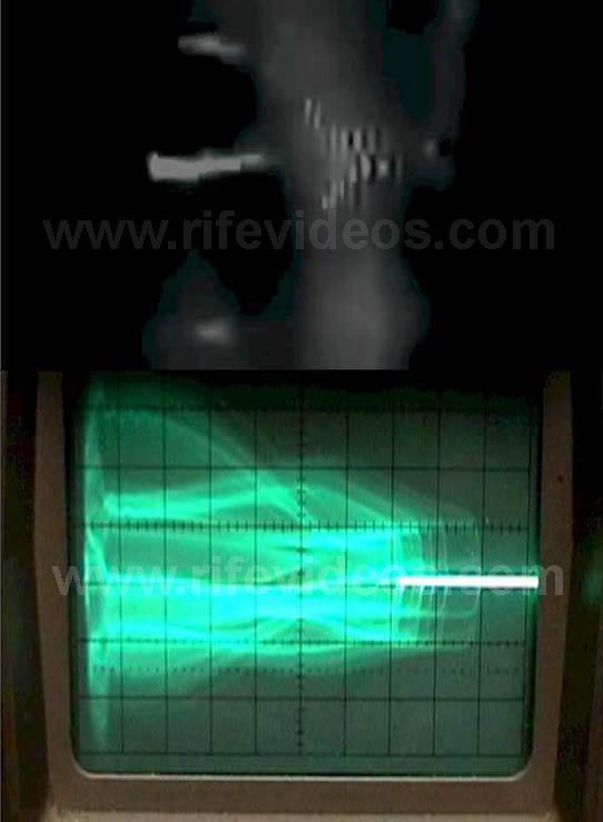
Photo Comparison To Earlier Rife Machine
Comparison of wave from original Rife machine (top) with the waveform from the Beam Rays machine. Note the similarities in the wave envelopes.
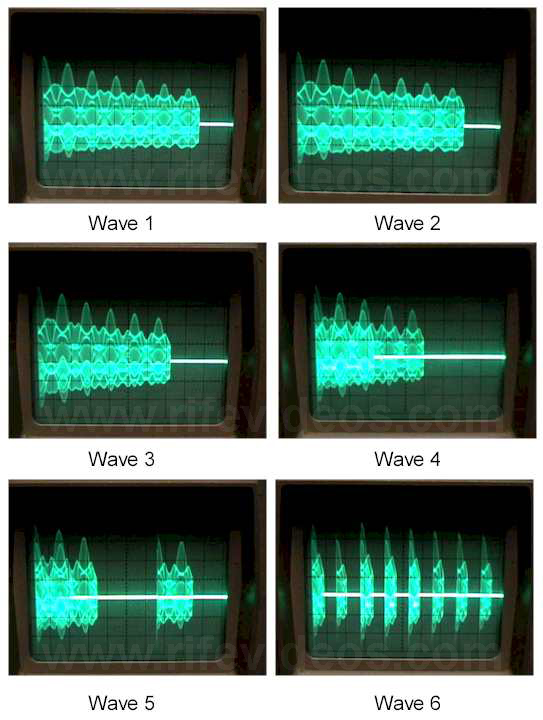
Effect of Modulation Depth
Wave 1 - this is one burst of the tank waveform at 1430 Hz (scope settings on uncalibrated and adjusted for better resolution) and in excess of 90% modulation depth (sine wave).
Wave 2 through Wave 4, this is what happens as the modulation depth is successively increased - Wave 4 is pretty much 100%. The number of cycles per burst (a burst is approx 20ms apart and is set by the mains cycle) decreases with increasing modulation.
Wave 5 - as you enter over modulation, the burst breaks up into smaller chunks.
Wave 6 - at approx 50V p-p modulation the wave is over modulated and consists of single cycle pulses grouped into bursts.
Analysis Of Beam Ray Machine Operation
Below is a more detailed description and brief analysis of the operation of the Beam Ray machine.
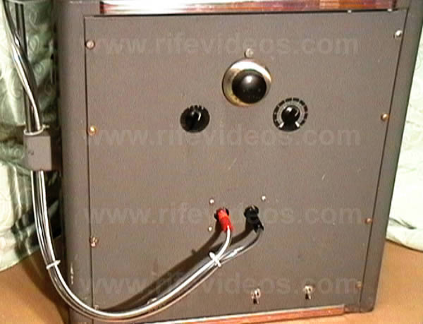
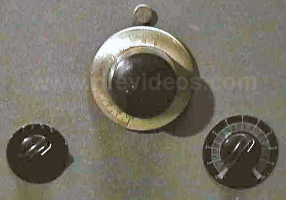
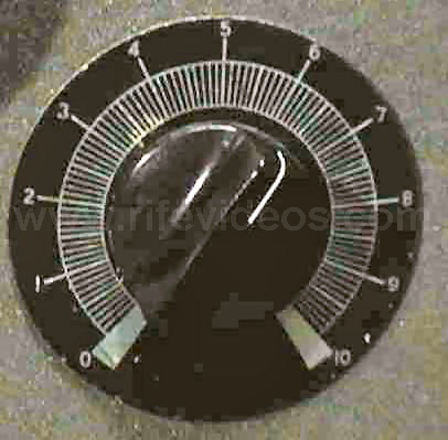
The machine has 3 external controls. The leftmost one is a 4 way rotary switch with positions labeled 1 through 4. These are the (modulation) frequency bands of the machine. The total range of the modulation settings is from approximately 20 Hz to 200 KHz in 4 decades as follows:
Band Frequency Ranges
Band 1: 20 Hertz to 200 Hertz.
Band 2: 200 Hertz to 2000 Hertz.
Band 3: 2000 Hertz to 20,000 Hertz.
Band 4: 20,000 Hertz to 200,000 Hertz.
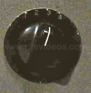
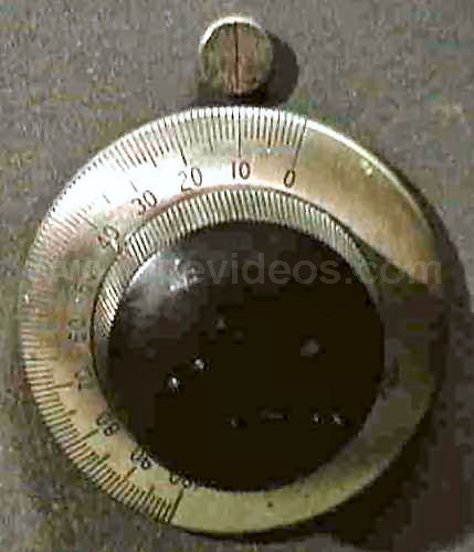
Main frequency Dial Adjustment
The center control is the main modulation frequency dial. This is calibrated in one step units from 0-100. The dial superficially appears to be a vernier dial but isn't, although it is finely marked, of good quality and is geared down, so a single turn does not move it completely from end to end. A resolution of 1/2 a division is easily possible.
Modulation Amplitude Control Dial
The right hand control is the modulation depth control. It varies the modulation applied to the grid of the output triode from 0 to 50 V p-p. The highest setting of 50V p-p is not 100% modulation, but rather over modulation of about 115%.
Treatment Settings
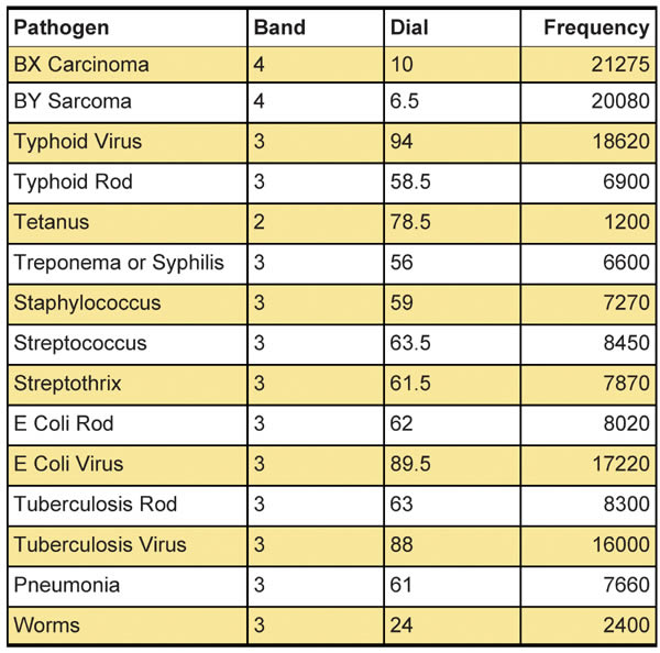
The machine came with some old diary pages with a series of treatment settings scribbled on them. The year of the diary was not shown, just the months but February was shown. It was not a leap year and by matching the days of the week to the dates it had to be 1939. There were the "usual" Rife pathogens plus a few more ailments that I had never seen quoted on any other early Rife machine list. Unfortunately they were not all complete so it wasn't possible to derive the true frequencies for all of them. The anomalies included:
"V" with a setting of band 3, dial 39 - but I have no idea what this is.
"Radiation" with a strange setting of "2-17-3" which could mean band 2 or 3 dial setting 17.
Pain - "20", Iodine Poisoning - "92", Mercury Poisoning - "55", Tissue repair - "58", Scar Tissue - "13", Mucous Colitis - "38", Hemorrhoid - "88", Catarrh - "17", Inflammation - "40" and Irritation - "30".
The ones that could be clearly resolved are shown in the table Below. The treatment frequencies are all approximately 10 times the ones listed in the modern Crane derived frequency lists for the various conditions.
Audio Frequency Circuit Analysis
The most striking thing about the Beam Rays audio frequency circuit at first glance is the oscillator section. The machine oscillator is clearly a first generation Hewlett Wein Bridge circuit. What makes this particularly notable is that Hewlett (Hewlett-Packard) only invented the circuit around the time the Beam Rays machine was built. Because it was so new and had not found its way into commercial designs it tends to imply that there might have been some connection between Hewlett and Beam Rays.
I have written a detailed account of the history entitled: "The Hewlett Connection"The earlier Rife machines had used the Hartley oscillator circuit which was no where near as stable as the Hewlett Wein Bridge. So the use of this circuit was a big step forward for Beam Rays. The earlier machines had been plagued with apparent frequency instability which made consistent use very difficult. The Wein bridge circuit was an apparent solution, but in practice there was another factor that they apparently did not take into account.
The Beam Rays oscillator is remarkably stable - it drifts by only a few Hertz during normal operation and is superior to many modern analog generators. But it has one major drawback. Tuning is achieved by way of a variable capacitor. This capacitor is connected directly to the tuning dial. The tuning dial is a geared down dial that allows very precise turning of the capacitor shaft. However in practice it suffers from a slight degree of "backlash" - in other words, no matter how carefully you turn the dial, there is always some residual pressure on the rotary shaft - and left to itself for a while this residual pressure or tension causes the capacitor shaft to turn back by a small amount. This is enough to throw the tuning out by a couple of Hertz in the lowest range - and the problem multiplies by a factor of 10 for each higher range. So in the top range the backlash can throw the frequency setting off by approximately 2 KHz. In addition, because the relationship between the dial setting and the actual frequency is non-linear, the problem is always worse toward the top of the scale (i.e. the dial is calibrated from 0 to 100 - the problem is much more pronounced near 100 than it is near 0). One of the ways in which this manifests most noticeably is that turning the dial down from a higher number results in a lower overall frequency than turning the dial up from a lower number to the same final setting.
The frequency setting is obviously critical and this may explain why some frequency stability related problems were encountered even with this extremely good oscillator.
The presence of the Hewlett oscillator explains also the general build of the machine. When I examined the machine there were various minor anomalies. One of which was the size of the two chassis. They are both much bigger than they need to be. Also there are two separate chassis and the earlier Beam Rays machines had only one. Another thing is that there is a circuit on the oscillator stage which is not connected and not used. This was probably meant to be able to create square waves by sine overdrive and clipping. Finally the mounting holes on the chassis do not correspond with the mounting holes on the case - someone has drilled new holes in both chassis to remount them in the case. This could mean that the case the machine is in is not the original case it was shipped in. Alternatively it could mean that the chassis were previously mounted in a different way (maybe in a different case) prior to shipping.
Taking all these things together leads me to the conclusion that the machine I examined is probably an original prototype. This makes sense considering that the Hewlett oscillator was so new. Obviously, Phillip Hoyland or whoever built the machine decided to try making the oscillator stage separately from the output stage. The output stage is presumably the same as in earlier Beam Rays machines (it looks the same as a 1937 Beam Rays machine), but clearly they decided to build the oscillator on a separate chassis. The chassis were overlarge to allow for circuit expansion and modification. The unused circuit was probably tested at some point and found to be unnecessary. And it is likely that during development the different mountings were used on some sort of open frame to allow testing and measurement.
But this prototype machine was shipped and sold as a finished unit, why? The answer is probably quite obvious. The machine was produced during the great depression. Everything was expensive; Beam Rays was a small company and needed to keep down costs. The prototype was probably only needed during development. Once everything had been worked out satisfactorily, the prototype was no longer needed - and could be sold for a substantial profit, as it was effectively a working machine of a new design.
The 6SJ7 and 6K6(B) tubes on the combined schematic are the basic Hewlett Wein Bridge oscillator circuit. See "The Hewlett Connection" for a schematic of Hewlett's patented design. The third tube marked 6K6(A) is a simple cathode follower buffer stage, analogous to a modern transistor emitter follower circuit. This circuit has high input impedance, low output impedance and unity gain. It is designed to insulate the sensitive oscillator section from the following output stages. The 6SN7 tube is the unused circuit and as mentioned above was probably meant to be part of a fast clipper amplifier to produce square wave modulation.
The oscillator stage creates a pure sine wave from approx 20 Hz to 200KHz depending on range and dial setting. It also produces a variable amplitude output which can be adjusted from 0v right up to approx 50V peak to peak.
The output stage consists mainly of a single power triode. Although the machine had an 812A triode in it when I got it, I believe the correct original tube was an 809. The machine runs a lot more cleanly and stably with an 809 than an 812A. The stage is self-oscillating; it has a simple regenerative feedback arrangement from plate to grid via two capacitors and the tank coil. The degree of feedback can be adjusted by means of a large power resistor from the grid to ground.
Note: the machine was not actually grounded, the negative end of the supplies connected to the chassis and all "grounds" were actually referenced to the chassis. I found in practice that the chassis did tend to accumulate quite a nasty residual charge after the machine had been operating and so I grounded it which did not seem to affect the operation of the machine. The output stage is actually a Hartley oscillator, although not obviously so, because the output capacitor in series with the plasma tube capacitance represents the "tuning" capacitance of the circuit. The large power resistor in series with the tube affects the oscillator loading, the output field impedance and also the Q of the resonant circuit. Because the plasma tube is an active circuit element, capacitive coupling from anybody in the vicinity of the plasma tube actually causes changes in the oscillator frequency. The "resting" frequency of the output oscillator is around 3.30 MHz using the 812A and an Argon (Nazarov) phanotron tube. When the tube was was changed to an 809 and a 15mm Helium Cheb phanotron was used, the "resting" frequency changed to 4.68 Mhz and the wave became much more sinusoidal .
The output from the modulation oscillator stage is capacitively coupled to the output triode grid via an inductor. The latter is designed to prevent the carrier oscillations from feeding back into the modulation oscillator stage.
The DC HT power for the output triode is derived from a 1235 VAC plate transformer by two 866 mercury vapour rectifiers. The DC output is smoothed via a large choke and a filter capacitor to ground. There is also an RFC choke in the line to the plate. The net voltage at the plate of the triode is only around 550V DC which is consistent with a choke smoothed circuit. However much more interesting is the other end of the tube - the filaments (which double as cathodes) are connected to a direct AC filament heater transformer which means that there is an additional modulation at the 60Hz mains frequency (cathode modulation).
In practice during operation, the machine creates the carrier waveform (which is not very clean and contains a lot of harmonics - it has a superficial similarity to a sawtooth wave).
UPDATE: the carrier waveform is smoother with the 809, but still contains some strong harmonics. The carrier is then amplitude modulated by the sine wave produced by the modulation oscillator. However, in addition, the AC cathode connection causes a further modulation at 60Hz. In effect the modulated wave is chopped into chunks or bursts that are one period of a 60 Hz cycle apart. And the envelope of the wave is effectively the first quarter cycle of a 60Hz cosine wave. In some respects this is like a very crude approximation to a damped wave. I believe that the latter is not a design flaw but rather a feature.