| Home | Accessory Kit | Marsh CD Collection | Library | Contact Us |
Chapter #9
1938 to 1939 Rife Ray #5 or Beam
Ray Corporation Clinical Rife Machine
1) The instrument used a ray tube.
2) Had one variable Audio oscillator and one Fixed RF oscillator set at 3.30 or 3.80 MHz.
3) Power usage was about 450 to 600 watts. Output to the ray tube 75 watts RF.
Just as with the Rife Ray #4 Rife Machine we must determine what the Rife Ray #5 or Beam Ray Corporation Rife Machine looked like. The reason we need to determine this is because unless we know what those instruments really looked like we may think we have a true Rife Ray #5 or Beam Ray Clinical instrument and find out later that it is not one. Beam Ray Corporation built two different instruments, one was called the Clinical instrument and the other was called the Laboratory instrument. The fact that Beam Ray built two different instruments was pointed out in the Trial: (Beam Ray Trial Transcript #209-210)COMPARET: “The four machines bought by the British were two so called laboratory types and two so called clinical types, what was the difference between the two?”
HOYLAND: “The clinical type was similar in all respects to the Rife machine except that it did not have [word missing] of the [word missing] used on Mrs. Henderson.”
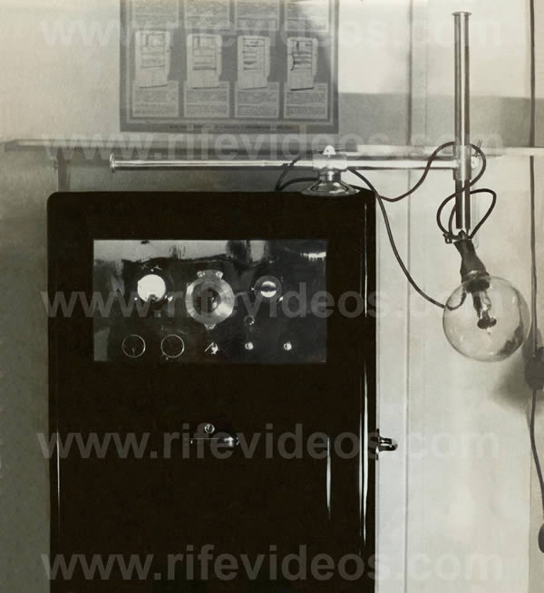
We now know that Beam Ray Corporation built two different Rife Machines of which one was built using the original Rife principles and it was considered the Laboratory instrument. The other was built using a different method of generating the frequencies and we will show that it was called the Clinical instrument. First, we will prove that the photo, shown above, and the next photo, shown below, are photos of the Rife Ray #5 or Beam Ray Clinical instrument.
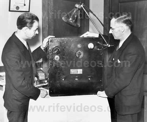
The instrument, shown above, is a photo of one of two Rife Machines owned by Dr. James B. Couche which he purchased from Beam Rays Corporation. Dr. Hamer also purchased one of these Clinical Rife Machines. This information was pointed out during the Trial and gives us the proof we are looking for: (Beam Ray Trial Transcript #98-99, 217-218, 1128-1131 and 2700)
COMPARET: “Before this agreement was signed did the company manufacture any Rife ray machines?”
HOYLAND: “They started to about the first of May [May 1, 1938]. Dr. Hamer was sold one.”
COMPARET: “How was the price of these machines fixed?”
HOYLAND: “The price was decided from the costs of what it cost to manufacture the first machine that was sold to Dr. Hamer.”
COMPARET: “Were the clinical machines the same as were made for Dr. Hamer?”HOYLAND: “Yes.”
COMPARET: “Was that the same as the machine used on Mrs. Henderson?”
HOYLAND: “No, but the same type.”
SAPIRO: “These machines are perfectly good; they are just the same as the [Dr.] Couche machine and the one that gave Mrs. Henderson such relief.”
These quotes show that Beam Ray Corporation sold the Clinical style Rife Machines to Dr. Hamer and Dr. Couche. In 1951 Dr. Couche sold one of his Beam Ray Clinical instruments to Dr. Tully.The above photo of Dr. Couche's machine and the documents we have read show us that his machine is an original Rife Ray #5 or Beam Ray Rife Machine. With this machine, we can make comparisons against it when looking at other instruments.
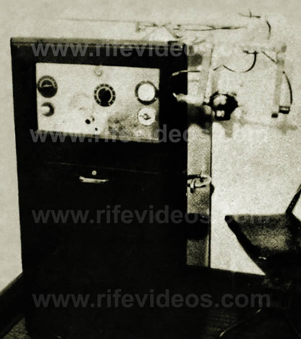
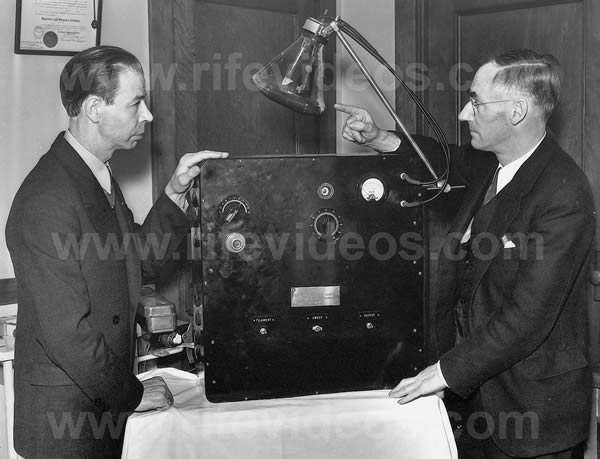
The next photo, shown below, is a picture of Dr. Rife and Philip Hoyland. Philip Hoyland was Dr. Rife's engineer and business partner in the Beam Ray Corporation. In this photo is an instrument. We will prove that this instrument is also a Beam Ray instrument by making some comparisons with other Beam Ray machines.
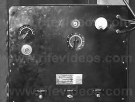
This photo of Dr. Rife and Philip Hoyland was taken for a May 6, 1938 newspaper article published by the San Diego Tribune. In the newspaper, the caption below the photo said: “Royal Raymond Rife, left and Philip Hoyland with Rife ray apparatus”. On May 1, 1938, the Beam Ray Corporation started selling its Rife Ray #5 or Beam Ray Clinical Machine to doctors. This front-page newspaper article had the capability of selling many instruments. It is only logical they would have photographed the instrument they were selling. The two photos, shown below, are close-up photos of these instruments. You will notice the similarities between these two instruments. They are almost exactly alike except for the case. Beam Ray used both types of cases with the Rife Ray #5 or Beam Ray Clinical instruments they sold.
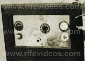
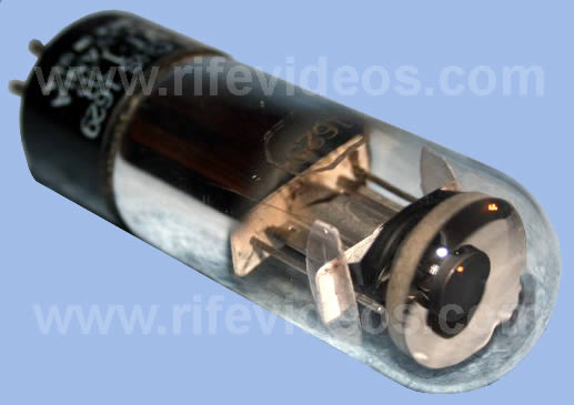
Dr. Couche’s Rife Machine, above on the right, was in a case that extended all the way down to the floor. It had handles on the side and wheels on the bottom which would make it very easy to move around. Both instruments have one oscillator dial which is located on the left side of the front panel. Below that dial on Dr. Couche’s instrument was a four-position band switch and on the other instrument, above on the left, is a fine-tuning dial. The fine-tuning dial was replaced by a four-position band switch in order to give the instrument better accuracy. The second dial, in the center of both instruments, goes to 100 and was the amplitude dial. Above that dial on both instruments is a tuning eye for calibrating the instrument’s RF carrier frequency. Below is a photo of one of these tuning eyes.
Both instruments have a milliamp power meter located all the way over to the right next to where the ray tube is connected. Dr. Couche’s instrument had a timer below the power meter to help him make sure he treated the patient for the correct amount of time. Along the bottom are the filament, sweep and output switches which are not clearly marked on Couche’s instrument but we can see what appears to be three different switches, two below the center amplitude dial and one below the timer. The comparison we have just made with Dr. Couche’s Beam Rays instrument shows they are both Beam Ray instruments. Beam Ray Corporation just put this Clinical machine into two different cases.
In the document "Development of the Rife Ray", we have a description of this Beam Ray Clinical instrument. We quote:
"In the early part of 1936 Commander Rife and Mr. Hoyland spent much time collaborating on revising some of the applications of the fundamentals of the instruments due to the advancement that had taken place in the application of electronics and it was found that the carrier wave used [Spark Gap] in the previous instruments could be eliminated.
During the summer of 1936 further experiments were carried on, which resulted in an entirely new method of generating the desired frequencies and produced a constant input and output in the instruments.
During this work several new test appliances were built for further studying the different frequencies and waveforms noteworthy among these was a 9 inch Cathode-Ray oscillograph of high sensitivity, built for the purpose of photographing the different frequencies on motion picture film and thereby allowing the numerous waves to be studied at will. During the fall of 1936 Dr. Couche of San Diego and Jack Free assistant to Commander Rife conducted a clinic with one of the frequency machines treating experimentally cases of carcinoma and senile cataract..."
(Development of the Rife Ray and use in devitalizing pathogenic micro-organisms).The first thing that we learn from this document is the high voltage spark gap method carrier wave that was used to light the ray tube in the Rife Ray #3 and Rife Ray #4 was no longer used or needed with the new 1936/1939 Rife Ray #5 or Beam Ray Clinical instrument. The document is correct because this style of the instrument only uses an RF carrier frequency to light the ray tube. The second thing we learn is that this instrument was working on an entirely new method of generating the M.O.R. frequencies. This method has been referred to over the years as harmonics. But it is more complex than what was originally believed.
This new method that was used to generate the frequencies has been a mystery for the past 75 years. Finally with the location and purchase of an original Beam Ray Clinical instrument and the use of spectrum analysis the method that Philip Hoyland used has been discovered.
In the first photo, below on the left, is the Rife Ray #5 or Beam Ray Clinical Machine that Dr. Rife and Philip Hoyland were photographed with for the may 1938 newspaper article. In the second photo, below on the right, is a picture of an original Beam Ray Rife Ray #5 instrument. This instrument was obtained from Dr. Larry Low. He has owned it for over 25 years and a friend of his owned it for ten years previous to that. This is the only known original Beam Ray Corporation Clinical instrument to have survived. It was used by a Medical Doctor who died in the mid 1960's.
We would like to thank Dr. Low for allowing us to get this instrument so we could analyze it. It is a low audio frequency instrument that uses an RF carrier frequency. This 1936/1939 Rife Ray #5 or Beam Ray Clinical instrument is very important. The significance of this instrument is due to the fact that it is the only known surviving original Rife Ray #5 Beam Ray Clinical instrument to exist. There were about 14 instruments built by the original Beam Ray Company and until now no one has ever been able to find one. The fact that even one has survived is a miracle. This instrument proves beyond any doubt that Philip Hoyland was the one who first built the low audio frequency instruments that were also built in the 1950s.
The next photo, below on the left, is also a Beam Ray Clinical instrument. This photo was found inside the case of the original Rife Ray #5 Beam Ray Clinical instrument obtained from Dr. Larry Low. The second photo, below on the right, is Dr. Couche's Beam Ray machine. Both of these Rife Machines are in the same case. If you look closely you will notice that both instruments have the same metal arm attached to the top of the instrument which holds the ray tube. This same arm is also on the top of the original machine obtained from Dr. Low.
In every detail, the cases are the same. The only difference between these two machines is the layout of the front panel. Though the panels are laid out differently both machines have the frequency dial, amplitude dial, band switch, milliamp meter, timer, power light, and two switches. It appears when Beam Ray Corporation built their first instrument, which was shown in the May 1938 newspaper photo, they had no band switches dividing out the audio frequency range. The doctors that used these instruments complained about the accuracy problems. It is apparent from the Beam Ray Trial testimony that a four-position band switch was added to help stabilize the audio oscillator and hopefully solve this problem. The original Beam Ray instrument that we obtained has a band switch with four settings. Aubrey Scoon’s Beam Ray Clinical replica instrument also has a four-position band switch. We will fully evaluate the Aubrey Scoon instrument later in this report. But we will refer to it from time to time as needed as we look at this original Beam Ray Clinical instrument. The 1953 AZ-58 Beam Ray Clinical replica, which we will also evaluate later in this report, had a three-position band switch. They only used a three-position switch because they used audio frequencies which were ten times lower than the original Beam Ray Clinical instrument. Because of this they did not need or use the fourth band, but doing this compromised the effectiveness of the instrument.
To further analyze the two original Rife machines we will now do a comparison of the faceplates. We will look at the instrument obtained from Dr. Low and the instrument Dr. Rife and Philip Hoyland were standing next to in the 1938 newspaper photo.
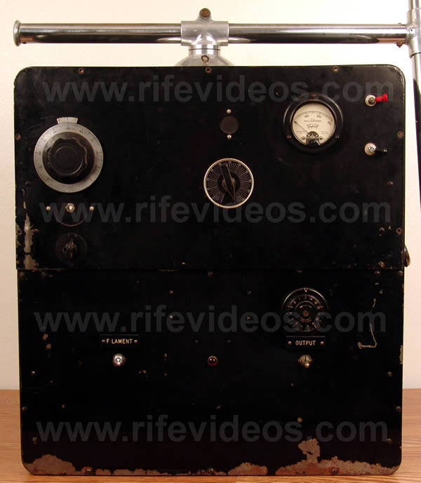
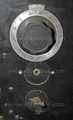
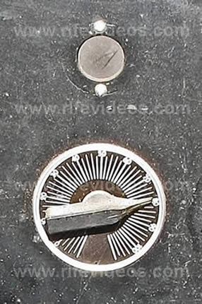
The first close up photos are of the variable audio oscillator control. The photo, above on the left, is the May 1938 photo. The photo, on the right, is the original instrument we obtained. Normally the dial should only go 180 degrees from 0 to 100 as shown on the May 1938 dial. Our instrument does not have the original dial because it goes from 0 to 100 in 270 degrees. Though the dial shows 270 degrees it will only go 180 degrees. You will also notice that our dial is bigger than the original dial and partially covers where the old fine adjustment dial was located. The fact that the hole is still there, but was covered, indicates that this instrument at one time worked the same as the instrument in the 1938 photo. When they added the four-position band switch the fine adjustment knob was no longer needed. Our Rife Ray #5 or Beam Ray Clinical Rife Machine, like Aubrey Scoon’s instrument, had four bands that cover these frequency ranges.
Band 1: 160 Hertz to 820 Hertz.
Band 2: 594 Hertz to 3,190 Hertz.
Band 3: 2,440 Hertz to 12,930 Hertz.
Band 4: 9,430 Hertz to 42,600 Hertz.
Aubrey Scoon’s Beam Ray Clinical Replica instrument band ranges, listed below, were different.Band 1: 20 Hertz to 200 Hertz.
Band 2: 200 Hertz to 2,000 Hertz.
Band 3: 2,000 Hertz to 20,000 Hertz.
Band 4: 20,000 Hertz to 200,000 Hertz.These four bands were discussed by Philip Hoyland and Bertrand Comparet during the trial: (Beam Ray Trial Transcript #257-260)
COMPARET: “If you wanted to treat one with typhoid for instance wouldn’t you have to set the machine so that it would be on a particular frequency.”
HOYLAND: “No, the machines were made so that they varied over a band of frequencies.”
COMPARET: “That band used for the treatment of each disease was different from other bands for other diseases, wasn’t it?”.
HOYLAND: “The whole list of bacteria that the machine was treating was divided into four bands.”
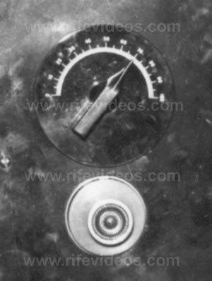
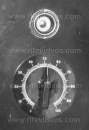
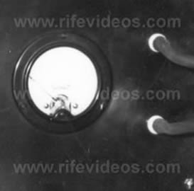
The next two photos, shown below, are of the tuning eye and the amplitude control. The photo, on the left, is from the May 1938 instrument. The photo, on the right, is our original Beam Ray Clinical instrument.
Above the amplitude dial on the photo of the May 1938 instrument is the tuning eye. On our instrument, you can see that the tuning eye was removed. Notice that you can still see the outline of the tuning eye mounting ring. On the May 1938 instrument the amplitude dial went from 0 to 100 and adjusted the audio frequency modulation. On our instrument the amplitude dial also goes from 0 to 100 and adjusts the modulation of all the audio frequencies. This modulation is not true (AM) amplitude modulation. It is more of a pulse width modulation.
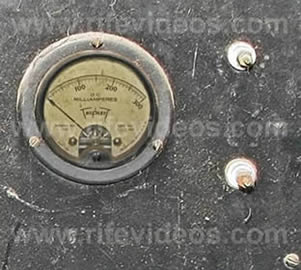
The next two photos, shown below, are of the milliamp meter that goes to 300 and the ray tube hookup. The photo below, on the left, is the May 1938 instrument. The photo, on the right, is our instrument.
Until the discovery of this Rife Ray #5 or Beam Ray Clinical instrument, we did not know exactly where the fixed RF tank coil was located. We thought it was probably behind the milliamp meter but now we know this is exactly where it was located.
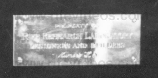
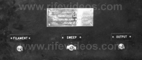
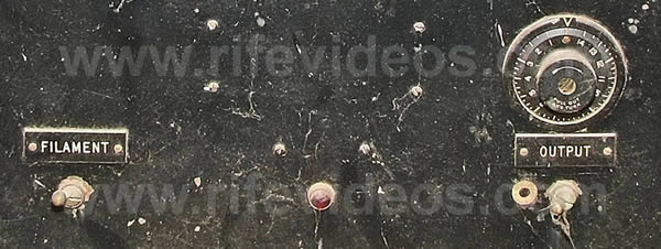
The next two photos, shown below, are of the plaque. The first photo is of the May 1938 instrument. The second photo is our instrument. These photos show where the original plaque was on the instrument.
The plaque read; “Property of the Rife Research Laboratory, Designers and Builders.” On our instrument, the plaque is missing but you can still see the four mounting screws that held the original plaque. Since this plaque had Dr. Rife's name on it this could have caused the doctor problems. So he may have removed it in order to avoid the machine being called a “Rife Machine.”
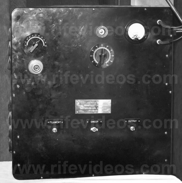
In the next two photos, shown below, you can see the “Filament”, “Sweep” and “Output” switches. The first photo is of the May 1938 instrument. The second photo is our instrument. On our instrument, the sweep plaque was removed and the switch was replaced with a red light that indicated that the instrument had power.
This is where the power indicator light was put on almost all of the instruments built during the 1940s and 1950s. The filament switch turned on the power to the 866 rectifier vacuum tubes and the output switch turned on the power to the 809 main amplifier vacuum tube section. Turning on the power to the 809 tube would light the ray tube. Because of the accuracy problems (due to the old (RC) resistor-capacitor audio oscillator) of the Beam Ray audio instruments the sweep switch was probably used to try and help solve this problem. The sweep switch appears to have been removed when the band switch was added. Above the output label on our instrument we see a 15-minute timer for setting the desired runtime for each frequency that was used. The Original 1938 Beam Ray Clinical instrument photo does not have a timer but Dr. Couche’s Beam Ray instrument shows his instrument had a timer on the front panel. Even the photo of the other Beam Ray Clinical instrument which was found inside our instrument has a timer built into it. These photos show that a timer was put in almost all of the original Beam Ray instruments..
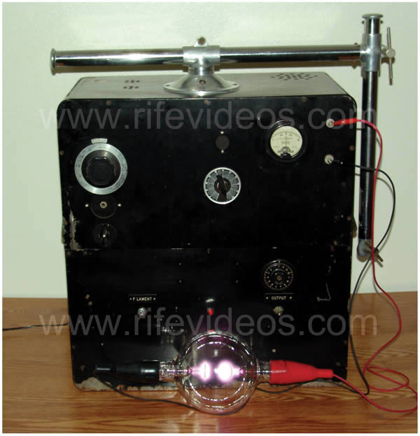
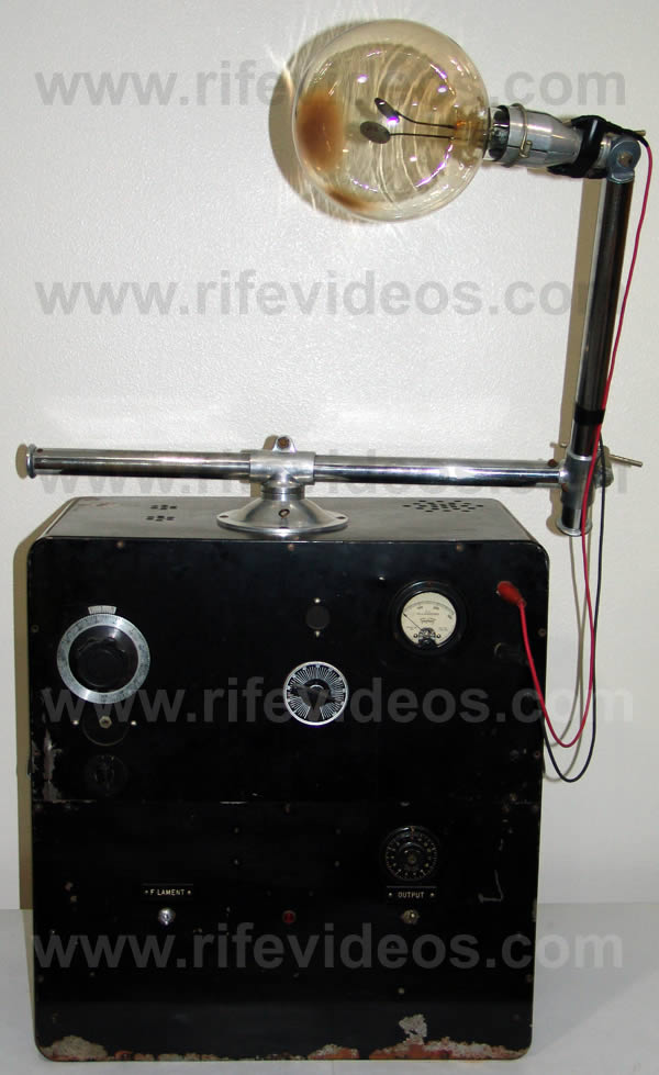
The next two photos, shown below, are of the Rife Ray #5 or Beam Ray Clinical Rife Machine obtained from Dr. Low. The first photo has the ray tube lit. The second photo has the original ray tube that came with the instrument when Dr. Low first obtained it over 32 years ago. This original ray tube did not come with the instrument when he gave it to us back in 2008. But in June of 2015, the original ray tube was finally found when Dr. Low moved to a new home. We wish to thank him for sending it to us. The tube is six inches in diameter but looks larger because of the angle of the arm it is connected to.
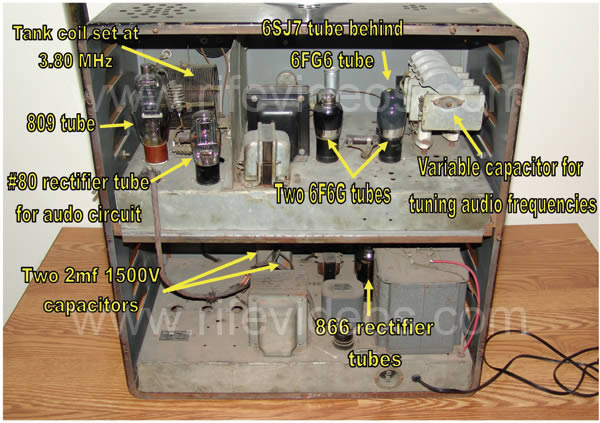
The next photo, shown below, is of the inside of the Rife Ray #5 or Beam Ray Clinical instrument. The RF tank coil of our instrument was set at 3.80 MHz. The 809 was the main output power tube. There were two 866 rectifier tubes.
The audio section consists of 2 6F6G tubes and one 6SJ7 tube. All of the Philip Hoyland audio instrument designs built from 1936 through the 1953's AZ-58 resemble each other. Anyone looking at the different instruments can see that they are all built almost in the same way. Tubes may vary, such as the 812a eventually replaced the 809, but the workings of all the instruments are similar. Both this original Beam Ray Clinical instrument and Aubrey Scoon’s Beam Ray Replica instrument have Hewlett Packard sine wave audio oscillators. Mr. Peter’s and I was able to repair the audio oscillator and read the different frequency band settings. It was only a 25 watt 10,000-ohm resistor which had burned out that made it so this instrument would not work.
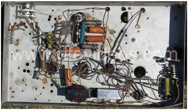
The readings for this report was done with this original 1936/1939 Rife Ray #5 Beam Ray Clinical instrument and so with Aubrey Scoon’s Rife Ray #5 instrument and the AZ-58 replica instrument that we built. They all work identically the same as the original instrument. This original Beam Ray Clinical instrument did not come with any paperwork which gave the dial settings for the various audio frequencies it used. This actually turned out to be for the best because we had no audio frequency data that could have stopped us from discovering how this instrument really worked on Dr. Rife's original high RF frequencies.The Next photo, shown below, is the underside of our original Rife Ray #5 or Beam Ray Clinical instrument. The underside of the chassis shows both the audio section and part of the RF section.
Now that we have an original Beam Ray Clinical instrument we know without any doubt that Philip Hoyland’s Clinical instrument design used audio frequencies and it modulated those audio frequencies onto a fixed RF carrier frequency.
Dr. Rife and Philip Hoyland had an agreement that they would share evenly on the financial profits of the instruments. Philip Hoyland stated this when he was on the stand during the Beam Ray Trial: (Beam Ray Trial Transcript #505-507)
HOYLAND: “Dr. Rife and I had always had the understanding that we shared evenly, as I had done all the development work.”
COMPARET: “What do you mean by that.”
HOYLAND: “I had done all of the building and designing of the machines other than the one original machine [Rife Ray #3 which consisted of the Kennedy equipment] that he had in his laboratory. I had brought that to a state where it could be carried around [Rife Ray #4].”From these trial statements, we know that all the designs were Philip Hoyland’s designs. When Hoyland built the audio instrument he built it on a completely different principle or method. Philip Hoyland had changed the instrument to work on a different method which used harmonics. Dr. Rife believed they were using the Rife Ray #4 RF frequencies along with harmonics. This was pointed out in the 1939 Beam Ray Trial (#1247-1250, 1278-1281):
COMPARET: “Has the Plaintiff [Philip Hoyland] ever informed you that the machines that he designed and built for the Beam Ray were not operating on the same frequencies as your own?”
RIFE: “They were supposed to be operating on the same with harmonics.”
COMPARET: “Did he ever tell you that there was a fundamental difference?”
RIFE: “He said on one or two occasions that there was a difference in harmonics.”
SAPIRO: “You say that the devices that were being built in the early part of 1938, the one that went to Dr. Couche and two that were in the lab were built on new harmonics?”
RIFE: “They were built on a different principal, we have a given wave length and it can be produced in different ways, but it should be the same no matter how it is produced.”
SAPIRO: “You knew that these machines were being built with that machine.”
RIFE: “Yes”
Philip Hoyland when he was on the stand was asked: (Beam Ray Trial Transcript #935-938, 953-958)
COMPARET: “I understand you say that the frequencies used in the machines put out by the corporation were not set to the same frequencies as Dr. Rife’s machines [Rife Ray #4].”
HOYLAND: “That is correct.”
COMPARET: “Did you inform the board of directors of Beam Ray that the machine you built was not the same as Dr. Rife’s?”
HOYLAND: “I had spoken to them about it.”
COMPARET: “Then it was during the period between September and November that you told Edwards at his home that the machines you were building were not putting out the same frequencies as Dr. Rife’s machines?”HOYLAND: “Yes.”
COMPARET: “How did you explain that?”
HOYLAND: “In the summer of 1936 I designed a new machine [The Beam Rays Clinical instrument], or rather I checked it there at the laboratory. I had designed it in Pasadena, and we tested it out then and the frequencies were not the same [they were higher harmonics of Rife's frequencies] as on Dr. Rife’s machine.”
COMPARET: “Did you tell him how great the difference it was?”
HOYLAND: “I explained that there was quite a fundamental difference.” [Higher harmonic frequencies of Dr. Rife's original frequencies]
Comparet when asked a question by Judge Kelly made this statement: (Beam Ray Trial Transcript #2673 & 2685)
COMPARET: “Hoyland has said that the design and the frequencies of the machine itself is not that of a Rife Ray machine, and that the machine is in fact different. The company will have to have these machines junked, must draw up new designs according to Dr. Rife’s ideas, must have Dr. Rife ok these designs, etc…Dr. Rife is not going to be a party to a fraud, and if the machines we sell are not the true Rife machines they are a fraud.”
When Edwards was on the stand he made this statement: (Beam Ray Trial Transcript #1384-1385)
COMPARET: “Did Mr. Hoyland tell you at any time in the fall of last year that the machines he was manufacturing for Beam Ray corporation operated on a principle fundamentally different from Dr. Rife’s machine?”
EDWARDS: “No, Mr. Hoyland told me at one time that Dr. Rife thought that he had the frequencies but he didn’t have them [here Edwards is talking about the Beam Rays Corporation instruments not the Rife Ray #4 instrument because Philip Hoyland said, on the stand, that he gave the Rife Ray #4 frequencies to Dr. Johnson and Dr. Rife in 1935].”
Philip Hoyland also stated this when he was on the stand: (Beam Ray Trial Tanscript #800)
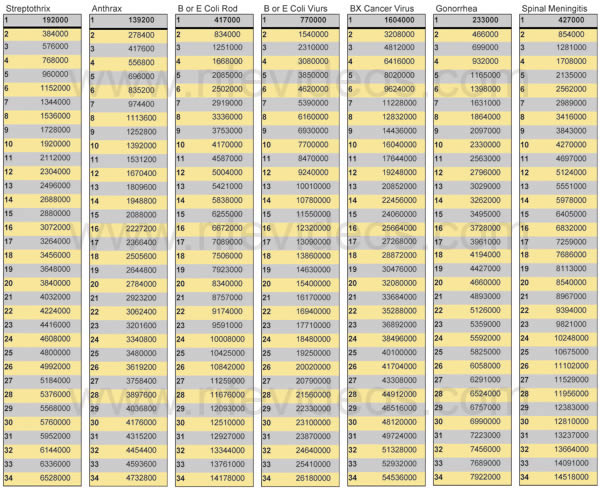
HOYLAND: “Regarding the frequencies of the machine [Beam Rays Corporation Clinical instrument], you will remember me telling you that the frequencies used are not the same ones on the Rife machine [The Rife Ray #4]. They [Meaning the Rife Ray #4 frequencies] were in the upper bands [139,000 to 1,604,000 Hertz].”
In a letter which he sent to Dr. Gonin in 1939, there are indications that Dr. Rife wanted the so-called harmonics removed:
RIFE: “I spoke only Friday evening to a Mr. John Chamblin, a radio man now connected with Beam Rays Inc., about the redesign and building of a device according to the old Rife Ray principles; as the present instrument has been so deviated away from that old principle that it is nowhere near the same...those devices which you have are merely working on a harmonic and not a true frequency; and in our research on electronics, we definitely know that there is no possible way of controlling electrical harmonics of a frequency.” (Letter from Dr. Rife to Dr. Gonin, May 14, 1939. Page 1 of 3)
We have just read a lot of trial testimony about how this Rife Ray #5 or Beam Ray Rife Machine worked on harmonic frequencies. Also, in the trial testimony, it is mentioned that these Beam Ray audio machines were tested in Dr. Rife’s lab to see if they would devitalize microorganisms. It was Philip Hoyland who made the tests using Dr. Rife’s organisms. These tests were also repeated again in Dr. Johnson's laboratory in the summer of 1936. From the documents we know that Philip Hoyland put a lot of work into this instrument and didn’t finish it until late 1936. Benjamin Cullen said Philip Hoyland spent a lot of time at the lab and stated the following in a taped interview in the 1950s:CULLEN: “Philip Hoyland was in there quite a lot...Hoyland developed some few items in the lab...Hoyland seemed to help quite a lot and he got into the bacteriology side with Rife a good deal because Rife had so much to work out...he finally got to the point where he [Dr. Rife] had to delegate some of the work.” (John Marsh Rife CDs, CD 6 track 1)
During the Beam Ray Trial Philip Hoyland testified that the Beam Ray Clinical instrument had been tested in the laboratory: (Beam Ray Trial Transcript #91 & 93)
COMPARET: “Were any experimental activities carried on in the lab?”HOYLAND: “Yes.”
From the trial, we learn that Philip Hoyland developed and tested his harmonic instrument in the lab. How could Philip Hoyland have tested it unless he put micro-organisms under the microscope? From the "Development of the Rife Ray" document we learned that:"During the fall of 1936 Dr. Couche of San Diego and Jack Free assistant to Commander Rife conducted a clinic with one of the frequency machines treating experimentally cases of carcinoma and senile cataract..." (Development of the Rife Ray and use in devitalizing pathogenic micro-organisms).
From the trial papers, we learn that Philip Hoyland didn’t tell Dr. Rife what frequencies he was using in the instruments. Dr. Rife thought the instruments we're using his frequencies (the upper band frequencies) but with harmonics because this is what Philip Hoyland told him. The information that we now have obtained from this original Rife Ray #5 or Beam Ray Clinical instrument shows that Philip Hoyland’s instrument was working on Dr. Rife’s principles and on his frequencies but in a different manner than Dr. Rife was lead to believe. This is the reason that the instrument worked so well. Philip Hoyland was still using Dr. Rife’s principle of coordinative resonance but hid the truth from Dr. Rife to protect his own interest. Philip Hoyland was a businessman and Dr. Rife was not.
The fact that these tests were done along with the fact that these instruments were used by many doctors with incredible results show that this instrument which used audio frequencies modulated onto an RF carrier frequency did devitalize microorganisms. Though Dr. Rife did not like the method of harmonic frequencies that Philip Hoyland used it was pointed out in the trial that Dr. Rife knew there were changes. Dr. Rife also didn’t think that these changes would make much of a difference as long as the instrument worked: (Beam Ray Trial Transcript #2700)SAPIRO: “Dr. Rife said that he knew there were changes made in his machine and that they were not changes that would make any difference. Dr. Rife is a genius but he didn’t know how to put the machines in a form that could be used in offices of doctors. These machine are perfectly good, they are just the same as the [Dr.] Couche machine and the one that gave Mrs. Henderson such relief.”
It was only with the release of the complete Beam Ray Trial manuscript and other Rife documents; found in California a few years ago that we now know why Dr. Rife continued to have this style of an instrument built even in the 1950s. Though Dr. Rife originally did not like Philip Hoyland’s Rife Ray #5 or Beam Ray Clinical design instrument, because of the use of harmonics, he later tested it in his laboratory and found it would work as well as his original instruments that did not use harmonics. We will quote the complete letter since all of this information is important:
Dr. Rife: My first association with Dr. Yale came through an organization known as the Beam Ray Corporation. In order to acquaint you with the details of the formation of this corporation I shall bring in a little background. My assistant at that time (1934) in the laboratory was Philip Hoyland whom I met through Dr, Milbank Johnson M.D., Medical Director for the Pacific Mutual Life Insurance Company. I considered Hoyland as a capable electronic engineer and brought him to my laboratory in Point Loma on Alcott Street, San Diego, Calif. Hoyland became associated with a promoter named Hutcheson and Dr. James B. Couche M.D. They came to me with the idea or forming the Beam Ray Corporation to manufacture and distribute the Frequency Instrument to the medical profession. I gave this considerable thought and came to the conclusion that if these instruments were manufactured and placed into the hands of legitimate and bonafide medical practitioners, my efforts, over a period of years would derive exceedingly more benefits, so I gave this corporation permission to manufacture these devices on two stipulated conditions (1) that they would adhere decidedly to the original basic principles of the Frequency Instrument and (2) that each Frequency Instrument would be thoroughly tested before delivery to determine its true devitalizing power and effect on pathogenic bacteria. And so they went ahead. Three instruments were built. The first two were shipped to England (unwired as Hoyland wanted a trip to England) and the third went to Dr. Hamer M.D. at the Paradise Valley Sanitarium and Hospital. Dr. Hamer was the superintendent there I believe. Hoyland was like many men with whom I have associated over a period of years. In a short time he began changing the basic principles of these instruments according to his own ideas. About this time he became associated with Dr. Yale and Yale ordered and received another or the Fourth Frequency Instrument. Since I was out of the city or San Diego at the time, all of these devices were delivered without being tested by myself.
At a much later period, I called on Dr. Yale at 333 Plaza in San Diego which was the address of his clinic at that time and told him that I did not feel that the Frequency Instrument had been calibrated properly so that it would not work. In the interim, I became associated with another electronist by the name of Verne Thompson, of San Diego. Under my supervision, Thompson rebuilt Dr Yale's Frequency Instrument which I tested in my research laboratory on pathogenic bacteria and the Frequency Instrument proved effective. Then later at different times I had this instrument checked and found it lacking in its ability to devitalize anything. I later learned that Dr. Yale had ideas of his own and would have somebody change the Frequency Instrument to suit his individual whims. I will state here definitely that I have never been associated in any way with Dr. Yale outside of the interest that I have taken in some of the patients of Dr. Yale." (Letter written by Dr. Rife, March 22, 1958)This document shows that Dr. Rife, after the shutdown of Beam Ray Corporation, eventually tested Philip Hoyland's Beam Ray Clinical design and found that it would devitalize all the microorganisms it was tested on. This also confirms that Philip Hoyland's statement that he tested it out in the laboratory was a truthful statement.
With this information taken from the Rife documents we now know why Dr. Rife considered the Beam Ray Clinical machine his instrument and knew it worked. Add to this the fact that all of the doctors who used it had a great deal of success with this Rife Ray #5 or Beam Ray Clinical instrument design. This is why Dr. Rife, John Crane and John Marsh built this Rife Machine in the 1950s and called it the AZ-58. The only difference in the 1953 AZ-58 design was it only had a three-band switch which covered a lower audio frequency range. Other than this change the 1953 AZ-58 was a replica of Dr. Couche's and Dr. Tully's original Beam Ray machine. In a letter dated July 6, 1956 this fact was pointed out:
"The Frequency Instruments used by Dr. Tully and Dr. Couche were built in 1938 and do not apply to this code. However the Frequency Instrument currently built are a copy of these earlier Frequency Instruments and are labeled "For Investigational Use Only" at the present time." (Application letter for approval of device in compliance with California Pure Drugs Act. Page 2)This information that we have just read which shows that the 1953 AZ-58 was a copy of Dr. Couche's machine has more importance than it appears. We will explain why. The 1953 AZ-58's audio frequencies, which it used, were 10 times lower than the audio frequencies used in Aubrey Scoon’s instrument. This correlation is important because it shows a direct link to the original Beam Ray Clinical instrument built by Philip Hoyland. This correlation shows that Dr. Couche's instrument used audio frequencies 10 times higher than the 1953 AZ-58. It also shows that Aubrey Scoon's Beam Ray Clinical replica instrument is also a replica or copy of Dr. Couche's Machine. This information now ties all these instruments together and shows that the original audio frequencies which came from Philip Hoyland and used in the Beam Ray Clinical instrument were the same audio frequencies used in Dr. Couche's machine and Aubrey Scoon's machine. This information also shows that these original audio frequencies were later lowered and used in the 1953 AZ-58 built by Dr. Rife, John Crane, and John Marsh. Now we can understand why this letter showing that the 1953 AZ-58 is a copy of Dr. Couche's machine is so important. It ties all these machines together.
Since we now know the history of this instrument and that this instrument worked on Dr. Rife's frequencies we will go back to the harmonic method used by Philip Hoyland. From the documents that we have read, we know that Hoyland's machine worked on harmonics. The problem with the Beam Ray instrument is it has to be built a certain way in order for it to work on the correct harmonics. It was from the analyzing of this original Beam Ray Clinical instrument that the mystery of how it worked was discovered. We will show how it worked after we read another important quote. Bertrand Comparet, Rife’s attorney who eventually defended Dr. Rife against Philip Hoyland in the 1939 Beam Ray trial said this about Philip Hoyland’s Beam Ray Clinical instrument:
COMPARET: “Well, none of us know enough about it. Now, I remember at that time Rife saying that Hoyland had not used a simple straight forward circuit, as Rife had used, but he thought he had a short cut, through use of harmonics and so on, and Rife had no faith in Hoyland’s circuit”. (1970's Bertrand Comparet interview #28)
This statement by Bertrand Comparet and all the quotes we have read sums up Dr. Rife and his Beam Ray business partner's understanding of how this instrument worked on harmonic frequencies. Anyone can see that only Philip Hoyland knew how this machine really worked and he would not reveal the secret to anyone.This confusion of how the instrument worked still remained throughout the building of the 1940's and 1950's Beam Ray replica instruments and even up until 2010. It appears from the Beam Ray Trial testimony that Dr. Rife and the other owners of Beam Ray Corporation really didn’t know how this instrument worked. The trial testimony shows that Philip Hoyland would not tell anyone in the Beam Ray Corporation the frequencies used with the Clinical instrument or explain how it worked on harmonics. John Crane and John Marsh who worked with Dr. Rife didn’t understand how it really worked either. If Dr. Rife had really known how it worked then he would not have allowed John Crane and John Marsh to have a variable RF carrier frequency in the instrument. Having a variable RF carrier, in and of its self, is not the problem. Having a variable RF carrier frequency would be a good thing as long as you also understand that the audio frequencies have to be correctly matched to the RF carrier frequency in order to produce Dr. Rife's higher harmonic M.O.R. frequencies. The problems came about because John Crane and John Marsh did not have this understanding.
The reason why John Crane and John Marsh put a variable capacitor in the instrument was so that they could tune the RF carrier frequency in order to make the ray tube brighter. By doing this it also made it so they could change the RF carrier frequency from about 2.2 MHz to about 4.9 MHz. This change showed that they did not understand how the instrument worked. They mistakenly believed that the audio frequencies were the M.O.R.s. or the frequencies that would devitalize the microorganisms. They also mistakenly believed that the RF carrier frequency was not important. This belief shows without any doubt that they did not understand how the Beam Ray Clinical instrument worked. If they had really understood how it worked they would have never called any of the audio frequencies M.O.R.s.
At this point, we need to explain a few things. Philip Hoyland had very good reasons why he wanted to hide how this new Rife Ray #5 machine worked. He became Dr. Rife’s Engineer in 1935 when he built the Rife Ray #4. In 1936 Philip Hoyland also began building the Beam Ray Clinical instrument that would be sold in 1938 by Beam Ray Corporation. Philip Hoyland was worried about keeping the original frequencies a secret because he felt people would try to steal their technology. This concern of Philip Hoyland was not unfounded because Mr. Parsons of the British Group did try to steal their instrument. From the trial transcript we learn they had no way to patent the instrument because everything they were doing was in public domain in regards to the frequency generating equipment. Even the frequencies themselves cannot be patented. Philip Hoyland felt that he had to come up with a way to keep anyone from finding out what the true frequencies were. So he built the instrument a different way using harmonics to hit the harmonic frequencies of the Rife Ray #4 and Rife Ray #3 Kennedy equipment. Until a genuine Beam Ray Clinical Rife Machine could be found and tested, we would never know for sure how Philip Hoyland generated and used the harmonics in his instrument. Even though we now know that Aubrey Scoon’s instrument is a Beam Ray Clinical replica no one knew for sure that it really was a genuine replica. This confusion and the lack of having the chronological history of when and what type of instrument was built made it very hard to find the truth.Not only would Philip Hoyland not tell anyone how his instrument worked he also would not let anyone know the new frequencies he was using. Everything he did hid the frequencies. In the Beam Ray Trial manuscript, we read that he always used a code to give the frequencies. This code would work with the dials. No digital readout was available in those days like we have today.
Since no one was ever given the frequencies from Philip Hoyland this has led to many problems. Some of the later Beam Ray Clinical instrument replicas have different audio frequencies and this also has led to a great deal of confusion. Even John Crane was sending people different audio frequencies other than the standard set he used with the 1953 AZ-58. Because of the different audio frequencies used in these Beam Ray replicas we really didn't know which set of audio frequencies Philip Hoyland really used. So it was not possible to use any of these frequency sets and come to any reasonable conclusions.
When we obtained this original 1936/1939 Rife Ray #5 Beam Ray Clinical Rife Machine, from Dr. Low, we had to put aside all the frequency lists and thinking of the past in order to figure out how the instrument worked. From everything we had read about Philip Hoyland’s instrument, we had come to the conclusion that the answer would be found in the math. However Hoyland came up with his idea it had to be a mathematical method. Like many others we tried to reconcile the audio frequencies as lower harmonics of Dr. Rife’s original high RF frequencies. But this proved not to be the case. We tested the frequencies that were used in Aubrey Scoon’s Beam Ray Clinical instrument and they didn’t match either as harmonics of Dr. Rife's original frequencies. We did the same with the AZ-58 audio frequencies and they didn’t match. We took the other audio frequencies that Crane had a list of and they also didn’t match. There is an instrument known as the 1947 instrument which we tried to reconcile with no success either. With all these audio frequencies only a few were close harmonic matches. If all these audio frequencies were true harmonics of Dr. Rife’s original high RF frequencies then they should have harmonically match up, but they did not.
Once we put all this aside and began to analyze this instrument we found out how it worked. This Beam Ray Clinical instrument is truly a harmonic instrument and works on harmonic frequencies of Dr. Rife's original frequencies which he found. Philip Hoyland was telling the truth when he told Dr. Rife that the instrument was working on harmonics. The only thing was Philip Hoyland would not tell exactly how this was being done. The fact that both the audio frequency and the RF carrier frequency were sine waves did not make it easy to understand how it worked. How could it be a harmonic instrument when it used a sine wave waveform for both the audio and the RF frequencies? The 1953 AZ-58 Beam Ray Clinical replica worked on square wave audio frequencies and the harmonics came from the square wave waveform. But this is not how the Beam Ray Clinical instrument was supposed to work.The 1950’s square wave method has been used ever since the 1950s. But how can an instrument that uses sine wave audio frequencies be a harmonic instrument? With this understanding we knew that the audio frequencies could never be the true M.O.R.s. But how did they work in the instrument to produce Dr. Rife's M.O.R.s? The harmonic square wave method has been an accepted method for many years. For many years almost everyone has understood and has generally accepted that you can take a square wave audio frequency and the harmonics it creates and hit a higher frequency M.O.R. through those harmonics. These audio frequencies are usually many hundreds of harmonic steps lower than the higher M.O.R. frequency. This harmonic method must be kept in mind as well as the fact that not once, but several times, in the Beam Ray Trial manuscript and other documents everything said about this machine showed that it was using the harmonic method. We must remember that Dr. Rife said that he believed that many of his frequencies were sub-harmonics of a higher frequency. He said if we knew the true higher frequency it may even work better. Because of how this instrument works it is logical to conclude that Philip Hoyland understood this concept and apparently found through testing that all of Dr. Rife’s frequencies were sub-harmonics of higher frequencies. With this understanding he built the Rife Ray #5 or Beam Ray Clinical instrument. Philip Hoyland was being truthful when he said that this machine was using harmonics. With all this knowledge from the Trial testimony and the Rife documents we now have a good understanding of the facts behind this new instrument design. Here is what we found when we analyzed the Beam Ray Clinical instrument.
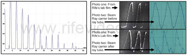
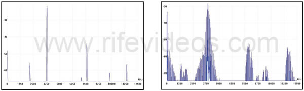
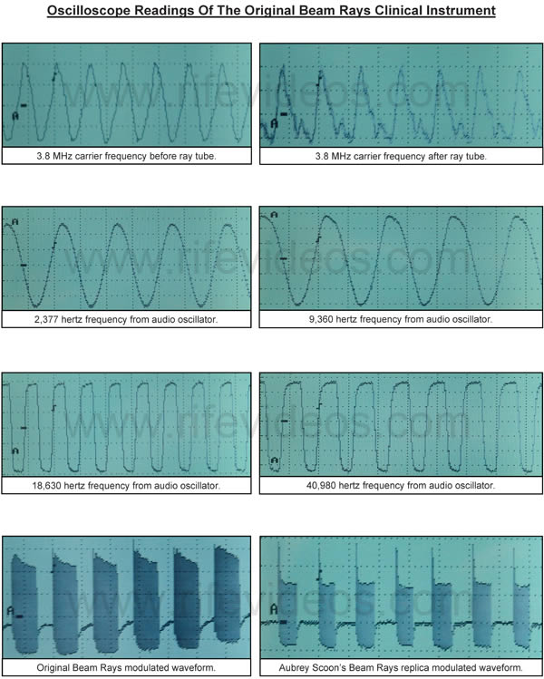
The graph, below on the left, is of the harmonics from the 3.80 MHz RF carrier frequency coming out from the ray tube of our original Beam Ray Clinical instrument. It was taken using a PicoScope 3205 spectrum analyzer. The first photo, below on the right, with the black waveform, comes from Dr. Rife’s 1939 lab film. The photo to the right of that photo is an oscilloscope reading that we took of the waveform of the Beam Ray Clinical Rife Machine. You will notice the similarity of the waveforms. All the M.O.P.A. (Master Oscillator Power Amplifier designs used by Philip Hoyland) RF carrier waveforms we have tested look like this. When you put a non-harmonic sine wave into a ray tube you will always see a distortion of the sine wave which will produce both odd and even harmonics through the ray tube. This is the reason the sine wave looks distorted.
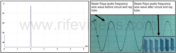
The graph, below on the left, is of a pure 2000 Hertz sine wave frequency. The oscilloscope photo, below on the right, shows a 2377 Hertz sine wave waveform coming from the audio oscillator of the original Beam Ray Clinical Rife Machine. The small photo shows it after it goes through the ray tube. You will notice that it almost looks like a square wave, but it is not. The circuit creates this waveform.
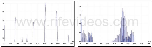
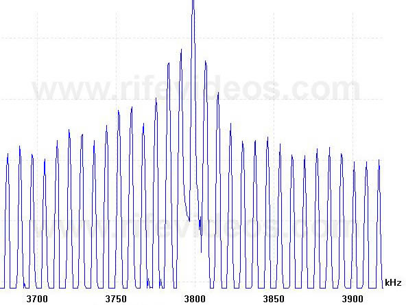
The graph, below on the left, was before modulation. The graph, below on the right, during modulation. When we modulated 40,000 Hertz on a harmonic sine wave 3.80 MHz RF carrier frequency this is what the PicoScope spectrum analysis showed coming out of the ray tube. This was interesting to see. Not only did it create sideband frequencies 40 thousand Hertz above and below the harmonic 3.80 MHz carrier frequency but it created many harmonic sidebands every 40,000 Hertz. These harmonic sidebands covered a large frequency range of hundreds of thousands of Hertz. Below are two more graphs showing a closer view of these sidebands that were created from one audio frequency.
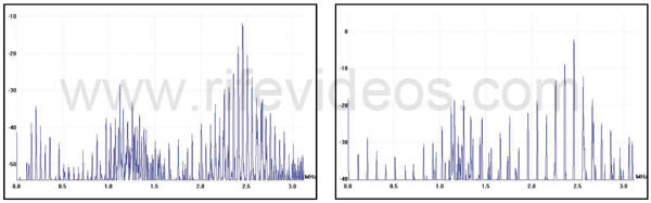
The graph, below on the left, is with a 50,000 Hertz sine wave frequency. The graph, below, on the right, is with a 100,000 Hertz sine wave frequency. This was done with a harmonic sine wave 2.4 MHz RF carrier frequency so you can see a closer view of these sidebands. When we saw this we knew there was only one way this Beam Ray Clinical Rife Machine could work on Dr. Rife’s frequencies and principles. We will now explain how Philip Hoyland’s Rife Ray #5 or Beam Ray Clinical instrument worked using a fixed RF carrier frequency of 3.80 MHz and a variable audio frequency. Philip Hoyland knew from working with Dr. Rife that his frequencies or M.O.R.s. were sub-harmonics of true higher frequencies. Understanding this must have given him the idea of how to build the new Rife Ray #5 or Beam Ray Clinical instrument. If we also understand this concept, that all frequencies have lower and higher harmonic frequencies, is half the key to understanding how Philip Hoyland made this machine work. What Philip Hoyland did was multiply Dr. Rife's original M.O.R. frequencies up in harmonic steps until he had the highest harmonic frequencies closest to 3.80 MHz. From the Beam Ray Trial quotes, we know that Dr. Rife was told by Philip Hoyland that this Beam Ray Clinical machine was working on his frequencies with harmonics. What Philip Hoyland would not do is clarify exactly how it was working on harmonics of Dr. Rife's frequencies. Philip Hoyland also stated that his frequencies were not the same frequencies as Dr. Rife's frequencies. He was being truthful when he said this but what he would not reveal is the fact that his frequencies were exact harmonics of Dr. Rife's frequencies.
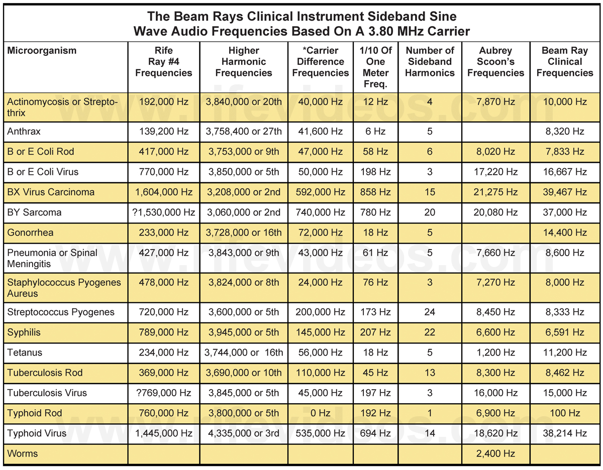
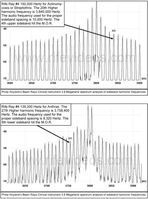
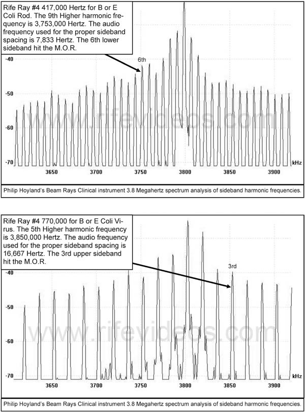
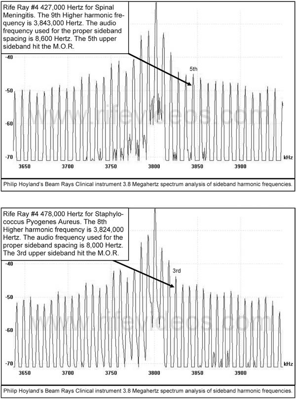
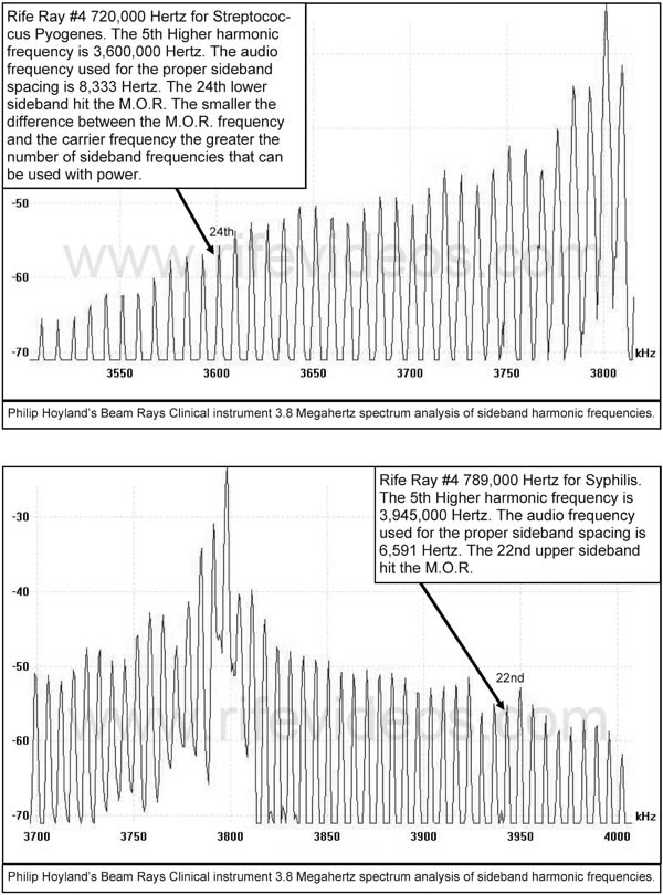
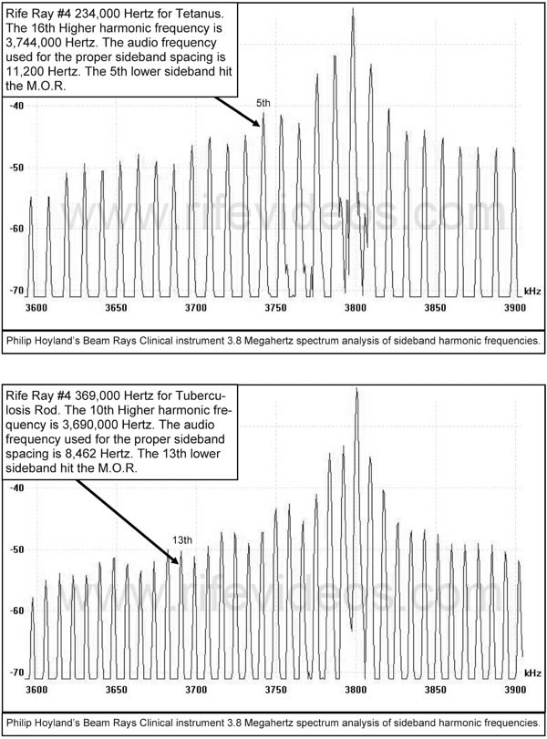
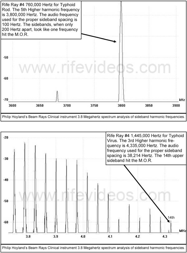
To clearly explain how Philip Hoyland used Dr. Rife's frequencies to come up with his new frequencies which were to be used in the Rife Ray #5 or Beam Ray Clinical instrument we will use the Rife Ray #4 frequency for Streptothrix as an example. That frequency was 192,000 Hertz. Philip Hoyland multiplied 192,000 Hertz by 20 times which will give you the 20th harmonic frequency at 3,840,000 Hertz. Since the RF carrier frequency of the Beam Ray Clinical instrument was fixed at 3,800,000 Hertz the difference would only be 40,000 Hertz between the two frequencies. This method of multiplying Dr. Rife's frequencies up in harmonic steps and using those frequencies was an ingenious method used by Philip Hoyland. Even though this was an igneous method it is only half the mathematical equation. The second half of the mathematical equation is probably even more ingenious than the first part.
Philip Hoyland then put into this Beam Ray Clinical instrument an audio oscillator. We must keep in mind that none of Dr. Rife's frequencies that were transferred from the Rife Ray #3 to the Rife Ray #4 and then to the Rife Ray #5 or Beam Ray Clinical instrument were audio frequencies. The audio oscillator was put into this instrument to accomplish the second half of the mathematical equation. Using the audio oscillator all Philip Hoyland had to do was use an audio frequency of 40,000 Hertz. The 40,000 Hertz frequency would then create what are called sideband frequencies. These sideband frequencies would be created by the 40,000 Hertz both above and below the RF carrier frequency being used. The first upper sideband frequency would then be 40,000 Hertz above the RF carrier frequency and hit the harmonic M.O.R. frequency of Streptothrix at 3,840,000 Hertz. This method of using sidebands was the second half of the mathematical method used by Philip Hoyland in this Beam Ray Clinical instrument. Now for further clarification of these sidebands, as shown in the photo above, which extends out many times above and below the RF carrier frequency depending on the audio frequency which is used. They are like pickets on a fence and every picket represents a harmonic sideband created from the audio frequency. These harmonic sidebands are part of the harmonics that the Rife Ray #5 or Beam Ray Clinical instrument used. So Philip Hoyland took Dr. Rife's frequencies and multiplied them up in harmonic steps as close as he could get them to the fix 3.80 Megahertz RF carrier frequency. Then these new higher harmonic frequencies of Dr. Rife's original frequencies then became Philip Hoyland's new M.O.R. frequencies which he would not reveal to Dr. Rife or any of his Beam Ray Corporation partners. Next he then used harmonic sidebands to hit those new higher frequencies.
Though Philip Hoyland's new frequencies were harmonic frequencies obtained from Dr. Rife's original frequencies they did not create harmonics in the Beam Ray Clinical instrument. The harmonics came from the RF carrier frequency and the harmonic sidebands created from the audio frequencies, which Philip Hoyland used. By using both of these methods combined into an instrument Philip Hoyland could then say that the Rife Ray #5 or Beam Ray Clinical instrument was a harmonic instrument capable of outputting Dr. Rife's frequencies. His method was truly a harmonic method but he kept it as a secret from Dr. Rife and the other owners of the Beam Ray Corporation. The sideband method that Philip Hoyland used was the new cutting edge of electronic technology back in 1936. There would be very few people who could understand what Philip Hoyland was doing unless it was fully explained to them as we have explained here. The proof of this is that no one has discovered it until now.
We will now explain Philip Hoyland's method further so that there can be no misunderstanding. But first what needs to be pointed out here is this IMPORTANT fact which came from the analyzing of this Beam Ray instrument. Neither the harmonic 3.80 MHz RF carrier frequency nor the audio frequencies will do anything by themselves. But when the harmonic 3.80 MHz RF carrier frequency and the audio frequencies are combined together they will produce many sideband frequencies. And one of these sideband frequencies will line up with the true higher harmonic Rife M.O.R frequency and devitalize or render harmless the harmful microorganism. To re-emphasize this so that no one misunderstands. If you just use the audio frequencies by themselves you will get nothing. If you just use the 3.80 MHz RF carrier frequency without the audio frequencies you will get nothing. The audio frequencies used in this instrument must have the RF carrier frequency of 3.80 MHz or they will not produce Dr. Rife's frequencies. This is the reason the 1953 Beam Ray Clinical instrument called the AZ-58 did not work properly. In that instrument, they were only using the audio frequencies without correctly matching them to the RF carrier frequency. In other words they were not using the sideband method that Philip Hoyland originally developed to be used in this style of instrument.
We know that Philip Hoyland was trying to hide the true M.O.R. frequencies of the organisms from anyone who used the equipment. Twice in the Beam Ray Trial, it was mentioned that Dr. Rife had no ability to patent the Rife Ray tube instrument. The only secret was the frequencies and Philip Hoyland was trying to protect his and Beam Ray's interests. The third and final secret that Hoyland used to hide the M.O.R. frequencies will now be explained. Keeping the harmonic sideband method in mind Philip Hoyland could have just divided the 40,000 Hertz by two and used a 20,000 Hertz audio frequency. Then you would have one upper sideband at 3,820,000 Hertz and the second upper harmonic sideband at 3,840,000 Hertz. The 3,840,000 Hertz sideband would hit the 20th harmonic of 192,000 Hertz. Philip Hoyland could have divided it by three and used a 13,333 Hertz frequency. He also could have divided it by 4 and used a 10,000 Hertz frequency. If he would have divided it by five he could have used an 8,000 Hertz frequency. Divided by six he could have used a 6666 Hertz frequency.
We could go on but anyone can see the many variable frequencies that could have been used to create the correct sideband frequency. Also, because of the “one-tenth of one meter” factor that Dr. Rife mentioned you could add a few Hertz to each frequency without changing the frequency enough to make it so it would not work. This means you could change the 6,666 Hertz to 6,669 Hertz just to make things a little more confusing. By using this method Philip Hoyland could use many different audio frequencies to produce whichever number of sidebands he wanted to use. This would make it impossible to figure out which sideband was hitting the M.O.R. frequency that would devitalize the organism. By using this new method of using higher harmonic frequencies of Dr. Rife’s original frequencies and then using harmonic sideband frequencies Philip Hoyland was able to build a machine that would hide the frequencies from anyone. Philip Hoyland's method as anyone can see was ingenious.
We know that Philip Hoyland's method worked very well except that the technology of the mid-1930's did have a few drawbacks. Dr. Couche said that he had to sweep the frequency dial in order to get his instrument to work consistently. This is understandable since the 3.80 MHz RF carrier frequency will wander in a sweeping motion five hundred to one thousand Hertz up or down from the fixed RF carrier frequency. The audio frequency oscillator also varied. Bertrand Comparet in his 1970's interview said this about the Beam Ray Clinical instruments inherent frequency drift:
COMPARET: “Well, as they warmed up they’d shift frequency...Now, whether this was Hoyland’s inability to do better, or whether it was just inevitable in those days, I don’t know, but Hoyland’s devices did have that frequency shift as they warmed up. So, they had their problems. Now what Couche did, see, he would have cases where he would get an instantaneous cure, like that, and other times when the treatment just didn’t produce any results, because of the frequency shift. So, he would start in, he had from Rife (Hoyland dial settings) a set of the frequencies for several different diseases and he would tune it deliberately to one side of that frequency and then gradually tune it across to the other side making sure that somewhere in the process he crossed the correct frequency, even if the instrument wasn’t exactly in tune anyway. Well, when they hit the exact frequency they got amazing results.” (1970's Bertrand Comparet interview #10)
Again if you look at the first graph, above on the left, you will also notice that there are harmonic frequencies created from the 3.80 MHz RF carrier frequencies at 7.60 MHz and 11.40 Megahertz. These sideband frequencies as shown in the above photo, on the right, are created not only for the 3.80 MHz frequency but its entire harmonics. These harmonics continue all the way up to about 12 MHZ with reasonable power. This creates an interesting effect and shows that all the harmonics of 192,000 Hertz are being hit over the whole spectrum of about 12 megahertz. This is probably why this Beam Ray harmonic instrument worked as well as it did when they hit the correct frequency. This Rife Ray #5 or Beam Ray Clinical machine was definitely a harmonic instrument as Philip Hoyland had stated. It may have even exceeded Philip Hoyland's original concept.
Now going back to the audio frequency method of creating the sidebands that Philip Hoyland used. No one could ever determine the 20th harmonic frequency of 3,840,000 Hertz or the original Rife Ray #4 frequency of 192,000 Hertz using this method. The secret of the Beam Ray Clinical instrument and the frequencies that would devitalize the microorganisms could never be figured out unless you had the original Rife Ray #4 frequency of 192,000 Hertz. Only a spectrum analysis of this instrument made it possible to figure out what Philip Hoyland was doing. Without this modern technology, a person would have to be very knowledgeable about how frequencies and their harmonics worked.
The fact that it has taken this long, almost 75 years, to figure out how this Rife Ray #5 or Beam Ray Clinical Rife Machine worked is proof enough that the secret was well hidden. As pointed out earlier, Philip Hoyland would never tell anyone how this instrument really worked. If anyone changed the 3.80 MHz RF carrier frequency then the audio frequencies would not work. New audio frequencies would have to be calculated to match the new RF carrier frequency. Also, Philip Hoyland could have changed the audio frequencies any time he wanted for any machine in order to confuse anyone who had the equipment. Since the instrument that we obtained from Dr. Low is an original Beam Ray Clinical instrument then one would assume that its 3.80 MHz RF carrier frequency is the carrier frequency that was used with all the Beam Ray Clinical instruments. But we know that this is not the case because they used a different carrier for other machines. None of the audio frequencies used in all the replica instruments from the 1940s to the 1953 AZ-58 match up to the 3.80 MHz RF carrier frequency. With this understanding we also have to assume that the audio frequencies used in this original Beam Ray Clinical instrument were different than the 1940s and 1950's instruments. Aubrey Scoon’s instrument had a 3.30 MHz carrier frequency so if his machine is a replica of one of the original machines, which it is, then the audio frequencies would logically have to be matched to its 3.30 MHz carrier frequency, which they are.The 1953 AZ-58 technical data shows that it used a 4.68 MHz RF carrier frequency. But when the variable capacitor was put into the AZ-58, in about 1956, the carrier frequency then became variable. This made is so Dr. Robert P. Stafford could change the RF carrier frequency to different carrier frequencies. In Dr. Robert P. Stafford’s “Electromagnetic Field Therapy” report he said the following about the carrier frequency they used on his patients with the 1953 AZ-58:
DR. STAFFORD: “Radio Wave transmission is used as a carrier wave. We use between 3100 KC [3.10 MHz] and 3300 KC [3.30 MHz] (This does not appear to be a critical value). The carrier wave is modified with specific cycles per second modulations. We believe that the CPS is a critical value and it actually may prove to be the most important factor which this research may offer.” (Dr. Robert P. Stafford M.D. 1963 patient report).
You will notice that Dr. Stafford did not think that the RF carrier frequency was critical. He clearly states that they believed it was the “CPS” or cycles per second of the audio frequencies which were the most important part of making the AZ-58 work. If the AZ-58 was going to work on the sideband method that Philip Hoyland developed then the RF carrier frequency and the audio frequencies had to be correctly matched. John Crane and John Marsh at this time also did not think that the setting of the carrier frequency was important to make the instrument work properly. Dr. Stafford would have gotten his understanding from them. We now know that the proper setting of the carrier frequency was important. The audio frequencies used with the AZ-58 should have been recalculated to match its 4.68 RF carrier frequency because its carrier frequency was different than Aubrey Scoon Beam Ray replica instrument carrier or our original Beam Ray Clinical instrument carrier frequency. When the math is done to check the sidebands with the audio frequencies that were used with the AZ-58 it shows that those audio frequencies will not create the correct sideband spacing which will match up to the harmonic Rife Ray #4 frequencies. This is probably why Dr. Robert P. Stafford could not get the AZ-58 to devitalize any of the microorganisms he was testing in the laboratory. Here are two of his statements:
DR. STAFFORD: “Please excuse my format in the following letter for I intend to ramble a bit and forget strict grammatical dictum. I am writing you at this time partially because John Marsh informs me in a recent letter that you may be somewhat disheartened or at least worried about your role in the experimentations with the Rife Machine. Believe me, Dr. Edward I know how you feel for I too have been through this same feeling with this matter. I have observed clinical results after treatments with this gadget which I can scarcely believe myself. Yet, despite these good results, I have been confused by some rather simple failures such as a recent experiment which I conducted at Good Samaritan Hospital where we used the machine to treat some cultures of Staph Aureus and Strept. Fecalis. In this work we failed to inhibit growth at all or influence the cultures with the Rife Rx. I sent the results to John Marsh and asked for clarification and to be very frank I am not satisfied with John’s excuse of the failure as described by Dr. Rife. I am afraid I’m not a very good apostle for I’m getting some ideas myself on how this thing may work. I really wonder if this ultrasonic kills bacteria and virus at all or does it work like other forms of ultrasonic and merely stimulate the tissue in some unusual manner thereby improving the circulation and secondarily enhancing the body’s defenses against infection…To summarize some of this rambling: I feel that the Rife Ultrasonic Therapy has a very definitely beneficial effect on the human (and canine) body...I furthermore feel that we, as doctors of medicine, using this machine must remain constantly alert to the condition of our patient and vary the Rx as indicated.” (Dr. Stafford letter to Dr. Jeppson April, 1 1958)
DR. STAFFORD: “As yet, we have failed to “cure” any case of advanced, terminal malignancy. It appears in several instances that we may have impressed the disease favorably, temporarily. It is difficult to rule out the psychological, morale booster effect to the terminal patient when some definitive effort is made again in his behalf. However, several improvements have appeared to be more physical than emotional...All the patients in the series were treated with the same frequencies (e.g., 728 - 784 - 880 - 2008 - 2128). Perhaps these frequencies may be wrong, or only nearly correct.” (John Marsh Collection, Dr. Stafford’s Report on using the AZ-58, page 4)
If the incorrect audio frequencies were used with the 3.10 MHz to 3.30 MHz RF carrier frequency what Dr. Stafford M.D. reported is exactly what would have happened. From Dr. Stafford’s statement, we know that he did not think the RF carrier frequency was critical. If Dr. Rife had fully understood how Philip Hoyland had designed the instrument he would have never allowed John Crane or John Marsh to put a variable capacitor in its circuit without recalculating the audio frequencies for the new RF carrier frequency they wanted to use. Also they would not have lowered the original audio frequencies by a factor of 10 times and used them. The AZ-58 would have had a new set of audio frequencies correctly match to the new 4.68 MHz RF carrier frequency it was originally given in 1953. The new set of audio frequencies would then have been the correct audio frequencies that would create the proper sideband spacing. Dr. Rife would have also made sure that Dr. Stafford knew that the carrier frequency was critical. If John Crane and John Marsh really understood how this instrument worked they never would have wanted to change the 4.68 MHz carrier frequency. The 4.68 MHz RF carrier would have been a good carrier frequency if they would have used the correctly matched audio frequencies.
It is obvious they never really understood how the instrument worked or how the audio frequencies interacted with the carrier frequency to produce the M.O.R.s which would devitalize the organisms. They, like us, were under the false belief that the audio frequencies they were using were the M.O.R.s. They unknowingly promoted this idea because Philip Hoyland would never tell anyone how the instrument worked. We know that Dr. Rife knew that this Beam Ray Clinical machine somehow worked on his frequencies with harmonics but it is apparent that no one but Philip Hoyland really understood how the instrument worked on the sideband method.
With the new variable capacitor that John Crane and John Marsh put into the AZ-58, they could change the RF carrier frequency from about 2.40 MHz to about 4.90 MHz. Dr. Stafford told me personally, when I talked to him, that it did not make any difference which carrier frequency he used, they all worked the same. We will probably never know the full story of how these mistakes were made but it is obvious that no one but Philip Hoyland had the proper understanding of how the instrument worked. Since the AZ-58 used the square wave harmonics method rather than the harmonic sideband method it would have been better if Dr. Rife, John Crane, and John Marsh had used a true lower harmonic frequency of the Rife Ray #4 frequencies, but they didn't. Using the correct sub-harmonic audio frequencies derived from the higher Rife Ray #4 RF frequencies would have been a better approach. Those Rife Ray #4 sub-harmonic audio frequencies used with the square wave harmonics method, probably would have worked better than the incorrectly match 1950's audio frequencies they were using in the AZ-58. We should do the same today with our frequencies.All that we have discovered with the analyzing of this original Rife Ray #5 or Beam Ray Clinical instrument revels that the audio frequencies used with this equipment are not Dr. Rife’s true M.O.R.s. They are just the frequencies needed to produce the proper sideband spacing in order to hit the correct higher RF harmonics of Dr. Rife’s original M.O.R. frequencies. If the audio frequencies were the frequencies that would devitalize the microorganisms then logically all Dr. Rife’s frequencies would have been audio frequencies, but they are not. If these audio frequencies were Dr. Rife’s true M.O.R. frequencies then an RF carrier frequency would not have been needed and he would have never even needed to build a Ray Tube instrument. Dr. Rife would have been able to do all of his work with a simple frequency generator that would have had a frequency range of only about 25,000 Hertz. But this is not the case. Dr. Rife always said that almost all his frequencies were in the upper bands which match the Rife Ray #4 frequencies which covered a frequency range from 139,200 Hertz to 1,604,000 Hertz. None of those Rife Ray #4 frequencies where audio frequencies.
It is interesting to note that this Rife Ray #5 or Beam Ray Clinical instrument did not have a dedicated fixed audio pulsing circuit. This is also the case with the 1953 AZ-58. Aubrey Scoon mentions a sixty Hertz feedback pulse into the circuit of his instrument but he could not determine if the instrument was intended to work this way or if it was just a malfunction. When we built his instrument we could not get our instrument to work in the same manner as he did in producing this feedback, therefore we believe that it most likely was malfunctioning and was not intended to work in that manner. Since this original Rife Ray #5 or Beam Ray Clinical Rife Machine that we obtained didn’t work in this manner either and none of the other replica instruments work this way we believe that our conclusion is correct.
We know that Dr. Rife’s high RF frequency instruments such as the Rife Ray #3 and Rife Ray #4 used a fixed audio frequency pulsing circuit. This fixed audio frequency modulated the high RF frequency and was used to devitalize the organism. We have shown already in this report that this pulsed waveform was needed to devitalize the various microorganisms that Dr. Rife tested. The Beam Ray Clinical instrument did not use this circuit. The logical reason why it did not use this circuit is the modulated waveform created from the variable audio oscillator must have been sufficient to create the effect. The variable audio frequencies, which created the sidebands, would also pulse the waveform and this must have been sufficient to accomplish the same result. From this we can conclude that all that is needed is a modulated or pulsed waveform with the proper M.O.R. high radio frequency to devitalize microorganisms.
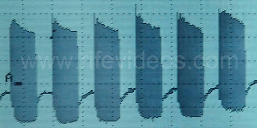
In the photo, shown below, is the Rife Ray #5 or Beam Ray Clinical instrument waveform. It looks almost like a modulated square wave waveform but it is not produced with a square wave. This waveform is produced using a sine wave audio frequency.
The Beam Ray instrument uses sine wave audio frequencies modulated onto a sine wave RF carrier frequency. It is the unique design of the Beam Ray Clinical circuit that produces this waveform. The M.O.P.A (Master Oscillator Power Amplifier) circuit that Philip Hoyland used was built in a different manner than would normally be used. Instead of using one vacuum tube for the RF oscillator section and a second vacuum tube for the amplifier section he only used one vacuum tube for both sections.
Because he used only one vacuum tube the circuit over oscillates and shuts off for half of the cycle. This shutting off for half of the cycle makes the waveform look almost like a square wave. This new waveform replaced the damped wave waveform that was used in the Rife Ray #4 instrument. In the 1953 AZ-58 Beam Ray Clinical instrument, the variable sine wave audio oscillator was replaced with a variable square wave audio oscillator. Had they really understood how the AZ-58 instrument was really supposed to work on the harmonic sideband method they probably would not have made this change. Changing the waveform from sine wave to square wave did not change how the harmonic sidebands worked in the AZ-58. It only shaped the waveform into a true square wave waveform. The only real change that could affect the output of the instrument is not matching the audio frequencies with the new 4.68 MHz RF carrier frequency. It was this change that proved to be the biggest mistake they made.
What must be kept in mind is the treatment frequencies were not the audio frequencies in the original Beam Ray Clinical instrument. It was the sideband frequencies created by the audio frequencies when matched and combined with the 3.80 MHz RF carrier frequency that would create the M.O.R. treatment frequencies. We tested both sine wave and square wave with the spectrum analyzer and there was no change in the sidebands. But in the 1950s John Crane and John Marsh were under the false assumption that the audio frequencies were the treatment frequencies.
Variable Audio Frequencies
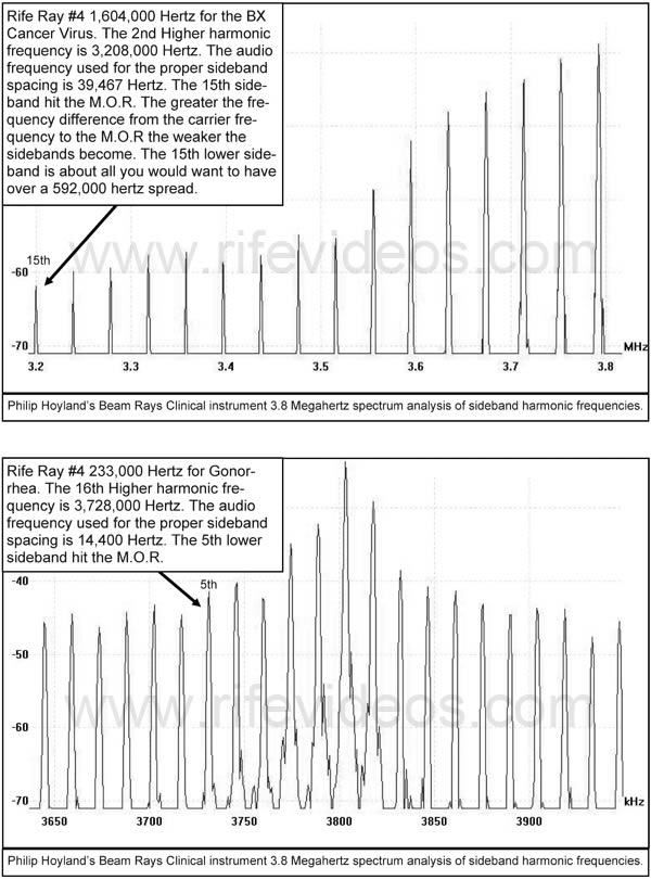
Now we will discuss the variable audio frequencies used in the Rife Ray #5 or Beam Ray Clinical instrument. When we figured out how this instrument worked on harmonic sidebands we did not choose the optimum audio frequencies. We just used audio frequencies that would show how the instrument worked. There are better audio frequencies that could be used for optimum performance to hit the Rife Ray #4 higher harmonic frequencies. In order to determine the audio frequencies that were used to create the sideband spacing frequencies we first had to determine the difference between the 3.80 MHz RF carrier frequency and Hoyland's new higher harmonic M.O.R.s. which were derived from Dr. Rife's original frequencies. In order to make it easier for the reader to understand the difference between the RF carrier frequency and Dr. Rife’s higher harmonic RF frequency we will call that frequency the “difference number” in this report. In most cases we divided, the difference number, by 5 but the BX was divided by 15. The BX M.O.R. higher harmonic frequency, based on the Rife Ray #4 frequency, is 3,208,000 Hertz. This frequency is only the second higher harmonic of the Rife Ray #4 frequency of 1,604,000 Hertz (1,604,000 X 2 = 3,208,000), so it will still work just as well as all the other frequencies.
A person must keep in mind that the modern square wave audio frequency harmonics are projected to hit frequencies hundreds of harmonics up. This Beam Ray instrument has far more power in its harmonic sidebands than any square wave harmonic has in it. And the Beam Ray instrument only has to go to the 15th lower sideband to hit the BX M.O.R. frequency, not hundreds of harmonics like a square wave harmonic would. This Philip Hoyland method would be far superior to using low square wave audio frequencies since the harmonics would all be 40 harmonic steps or less.
So that the reader can better understand how this instrument worked we need to determine what RF carrier frequencies would be best to use with this Beam Ray Clinical instrument. Philip Hoyland would have also done these calculations back in the 1930s. The best RF carrier frequencies to use would always be calculated based on Dr. Rife's highest original M.O.R. frequency. As an example the highest frequency that Dr. Rife used in the Rife Ray #4 was the BX cancer virus frequency of 1,604,000 Hertz. The best RF carrier frequency would be this 1,604,000 Hertz frequency multiplied by two which would be 3,208,000. So an RF carrier frequency in the 3.10 to 3.30 Megahertz range would be a good RF carrier frequency range. Dr. Couches’ Rife Ray #5 or Beam Ray Clinical instrument, built by Philip Hoyland, used an RF carrier frequency of 3.30 MHz and Aubrey Scoon's instrument which is a copy of it also used a 3.30 MHz carrier frequency. The importance of this 3.30 MHz RF carrier frequency will be discussed later. The next best carrier frequency would then be three times this frequency which would be 4,812,000 Hertz. So a carrier frequency in the AZ-58 4.68 MHz range would also work very well. By using Dr. Rife’s highest M.O.R. frequency it is easy to see that the best RF carrier frequencies can be determined. We are sure that Philip Hoyland had this same understanding.
Some of the following information was originally part of Chapter 8 but after restudying the Rife documents we found that this information, including the additional documents we found, actually should be in this chapter. This information confirms Philip Hoyland's use of higher harmonic frequencies obtained from Dr. Rife's original M.O.R. frequencies.
When Dr. Johnson and Philip Hoyland were testing the first prototype of the Rife Ray #5 or Beam Ray Clinical instrument in the summer of 1936 they had an interesting effect take place. At that time they were at Dr. Rife's laboratory testing different bands of frequencies on the various microorganisms. Dr. Johnson wrote about what happened in a letter he sent to Dr. Gruner on November 4, 1936. He also sent a copy of that letter to Dr. Rife:
DR. JOHNSON: “Last summer, in hunting for the M.O.R. for the other two reproductive forms of the cryptomyces pleomorphia, we ran into a new band of oscillations which introduced itself to us by killing all three forms - those that we called BX, our filter-passing form; then a transitional form such as you found in the monocytes in the blood; and then the third or highly developed form coming from the sporangius forming from the hyphas of the mycelium. At the same time that this new wave band arrived, we broke all the glass in the laboratory of a certain shape, not only in the room where we were working but in all the other rooms...we had been troubled a great deal with a mold because in the microscope room there were no windows, but this band not only destroyed that mold, which was growing on the leather objects in the room, but every bacteriological culture that we had in the laboratory! It cleaned us out completely so we had to start from scratch and replace our losses. In fact, we were all so surprised that we began to feel each other’s pulses to see if we were still alive. As no harm had been done to us, we proceeded to test the new band out on mice, rats, rabbits, guinea pigs and dogs. So far as we were able to discover, it is not at all destructive or injurious to normal cell tissue. While we have been forced to modify our machine so as to produce this new band, still it is so much more effective clinically that we look upon it as a very advantageous discovery. However, our experience has forced us to do all of our experimenting with the new ray [Rife Ray #5 or Beam Ray Clinical instrument] completely outside of our laboratory building or abandon all form of bacteriological experiments, because it instantly kills them all.” (Letter from Dr. Johnson to Dr. Gruner (copy sent to Dr. Rife) dated, November 4, 1936. Page 1, Page 2).Dr. Johnson clearly points out in this letter that this was done with a new Rife Ray. Dr. Johnson had been using the Rife Ray #4 since the fall of 1935 on his patients but here he points out that they were using a new Rife Ray machine and that it was clinically more effective than the machine he had been using up until this time. In the Beam Ray Trial documents Philip Hoyland stated that he had built a new Rife Ray instrument in the summer of 1936: (Beam Ray Trial Transcript #956)
HOYLAND: “In the summer of 1936 I designed a new machine, or rather I checked it there at the lab. I had designed it in Pasadena, and we tested it out then.” (Beam Ray Trial Papers).Also in another document called "Development of the Rife Ray" we have supporting evidence that a new Rife Ray was built in 1936:
"In the early part of 1936 Commander Rife and Mr. Hoyland spent much time collaborating on revising some of the applications of the fundamentals of the instruments due to the advancement that had taken place in the application of electronics and it was found that the carrier wave used in the previous instruments could be eliminated. During the summer of 1936 further experiments were carried on, which resulted in an entirely new method of generating the desired frequencies and produced a constant input and output in the instruments.” (Development of the Rife Ray).
With the Rife documents showing that Philip Hoyland built the new Rife Ray or Beam Ray Clinical instrument in the summer of 1936, we know that this was the machine that Dr. Johnson was referring to in his letter. In that letter Dr. Johnson clearly states that during the summer of 1936 they had tested this new machine in the laboratory. Dr. Johnson’s statement also confirms Philip Hoyland’s statement given in the Beam Ray Trial documents that the machine was tested in the laboratory. The documents all support each other and show that it was the Rife Ray #5 or Beam Ray Clinical instrument that they were using which produced this amazing effect. In this same letter Dr. Johnson stated, not once, but twice that this work was done with the new Rife Ray machine. Here is his other statement:
DR. JOHNSON: “I can assure you that no one, not even myself, could help but be astounded at the results we are now obtaining with the assistance of our new machines and our new band of MOR’s.” (Letter from Dr. Johnson to Dr. Gruner (copy sent to Dr. Rife) dated, November 4, 1936. Page 1, Page 2).This letter was written in November of 1936 a few months after the laboratory testing was completed on this new Rife Ray machine. They now had built more than one of these new machines as pointed out by Dr. Johnson when he said “our new machines.” Again Dr. Johnson points out that this is a new style of machine and it has a “new band of MOR’s.” In the Beam Ray Trial documents Philip Hoyland’s complete statement reveals that he was using different frequencies than Dr. Rife:
HOYLAND: “In the summer of 1936 I designed a new machine, or rather I checked it there at the lab. I had designed it in Pasadena, and we tested it out then and the frequencies were not the same as on Dr. Rife’s machine.” (Beam Ray Trial Papers #956).This statement made by Philip Hoyland about the frequencies not being the same as Dr. Rife’s original frequencies is confirmed by Dr. Johnson. So Dr. Johnson’s statement in his letter clearly shows that he understands that this new machine is using different M.O.R.s than what Dr. Rife was using in the Rife Ray #4. Dr. Johnson also points out that these new M.O.R.s are more effective than the original M.O.R.s found by Dr. Rife. Today we now know that these new M.O.R.s. that Philip Hoyland was using were based on Dr. Rife’s original M.O.R.s. They were just higher, more powerful, harmonics of Dr. Rife’s original frequencies. From the Beam Ray Trial, we know that Philip Hoyland stated that the frequencies he was using in this machine were not the same as the frequencies that Dr. Rife originally found. This, however, does not change the fact that all Philip Hoyland did was multiply Dr. Rife’s original frequencies up in harmonic steps to use them with this new Rife Ray #5 or Beam Ray Clinical instrument. Without Dr. Rife’s original frequencies Philip Hoyland would have had nothing. Probably the most important fact is the higher harmonics seemed to work better at devitalizing the organisms. As mentioned before, Dr. Johnson indicates in his letter that this new machine works better than any of the previous machines they had used up until that time (Rife Ray #3 and Rife Ray #4). His letter also shows that he is very impressed with the results they were obtaining with it. Another important fact we learn from this letter is Dr. Johnson now had the M.O.R. for the cryptomyces pleomorphia fungi. He had been trying to get Dr. Rife to find this M.O.R. for many months, without success, because Dr. Rife had developed eye problems and could not use his microscope. But now he had the ability to produce its frequency with the new machine. Another thing that Dr. Johnson pointed out was the fact that they had killed all the bacteriological specimens in his laboratory with the new Rife Ray machine and that they had to use it outside of the laboratory or it would kill all the new replacement specimens they had obtained.
Dr. Johnson in this same letter to Dr. Gruner said the following about this new Rife Ray machine which Philip Hoyland built:
DR. JOHNSON: “We are having a great time out here. I have opened a clinic in the Pasadena Home for the Aged and am having excellent luck. Of course, what I am trying to do is to experiment with the effect of the Rife Ray on bacteria in vivo. Our laboratory work has demonstrated pretty conclusively what it will do in vitro. The clinic is held three mornings a week, Tuesday, Thursday and Saturday. Yesterday I had eighteen patients. Among them were two cases of pulmonary tuberculosis, three cases of carcinoma, two cases of old chronic varicose ulcers of the leg, and sundry other cases of more or less definite infectious origins…I certainly wish that you were here to work with me because I am afraid that even you, who know what we are trying to do, will not believe some of the yarns that I would have to tell you as to what is occurring in the clinic without actually seeing them for yourself.”(Letter from Dr. Johnson to Dr. Gruner (copy sent to Dr. Rife) dated, November 4, 1936. Page 1, Page 2).Many people believe that Philip Hoyland’s Rife Ray #5 or Beam Ray Clinical machine was somehow inferior to Dr. Rife’s previous instrument's effectiveness in devitalizing microorganisms. But Dr. Johnson points out that this instrument was working better than any previous instrument they had used in the past. In another letter to Dr. Meyer, M.D. Dr. Johnson again talks about the effectiveness of this new Beam Ray Clinical machine:
DR. JOHNSON: “I am conducting a very interesting clinic three times a week with the Rife Ray, treating about twenty two patients a session, and we are obtaining much valuable information from our work. We are encountering many physical problems in the production of the Ray, the greatest difficulty being to obtain uniform results from the apparatus which we have. At times the results of the Ray are absolutely astounding, causing an instantaneous sterilization of the wounds whether interior or exterior. But owing to the slight changes in the temperature of the room and apparatus, the same setting of the dials does not give us the same output, and hence our results are unsatisfactory. However, we believe now that we have developed it to a point where we can very greatly diminish the errors in output and substantially increase the beneficial results or the effect of the apparatus.” (Letter from Dr. Johnson to Dr. Karl F. Meyer dated, December 7, 1936).Even with the calibration problems with the instrument, Dr. Johnson was still impressed with how well the instrument was working. If Dr. Johnson only would have had the ability that we have today to measure the frequency correctly, rather than relying on dial settings, he would have always had consistent results. With modern technology we can accurately measure a frequency regardless of any changes that the climate may make. Dr. Johnson only had the dial settings to work with back in the 1930s. The limits of the 1930’s technology would have given him the problems he talked about in his letter. Even with the limits of the 1930s technology, Dr. Johnson stated they had solved many of their problems with the instrument and this helped them to obtain even better results.
During this same clinic which Dr. Johnson was conducting he was also using this new Rife Ray on 30 cataract patients. In a letter that Dr. Johnson wrote to Dr. Joseph Heitger he stated the following:
DR. JOHNSON: “I closed my clinic on May 28, having been running it for eight months. Our special effort this past winter has been working on cataracts, and while we have treated a number of other infectious conditions (if cataract is an infection), still our principal work has been on the eye. We have had about thirty cases of cataract...Every case that we have treated, with the exception of one which was a traumatic cataract where the lens was absolutely opaque and of recent origin, has been benefited...The application of the Rife Ray as we have used it , does, in the great majority of cases restore the full visual function of the eye; that is, that portion of the visual disturbance due to opacities in the lens. How it does it and why it does it, I do not know, but the above statement is an actual fact, supported by many cases…Oh Lord; How I wish we could get together and go over this work! I believe it will result in epochal changes in the profession’s handling of cataract cases.” (Letter from Dr. Johnson to Dr. Joseph D. Heitger dated, June 1, 1937).In this letter to Dr. Heitger, Dr. Johnson again points out how well this instrument worked. In this letter, he also talked about the calibration problems they were having with this new Rife Ray machine. The Beam Ray Clinical machine was known for its calibration problems. Even the Beam Ray Trial testimony and other documents show that this instrument had calibration problems. Eventually Philip Hoyland divided the audio frequency range of the Beam Ray Clinical instrument into four bands. This helped but did not solve the problems completely. By the early 1940s, the audio oscillator was replaced by the new stable Hewlett Packard audio oscillator. This Hewlett Packard audio oscillator was far superior to the original RC (Resistor Capacitor) style audio oscillator used by Philip Hoyland. Had they had a modern frequency counter they could have easily solved any of the calibration problems they had. Today if anyone builds this instrument they would want to have the ability to check the RF carrier frequency so that they will have consistent results.
Next, we will explain how this instrument had the ability to devitalize so many organisms as described by Dr. Johnson in his letter. He stated in his letter of November 4, 1936 that it was done using a “new band of oscillations.” This happened at the time they were testing this new Rife Ray #5 or Beam Ray Clinical instrument at Dr. Johnson’s laboratory. Since it was a prototype machine we do not know what the original frequency range of the audio oscillator was when this happened. What we do know is the original Beam Ray Clinical instrument which we obtained from Dr. Low had four frequency bands which covered a frequency range from 160 Hertz to about 42,000 Hertz. Whether it was one of the lower bands or one of the higher bands we do not know. But this we do know, Dr. Johnson would have had this band put into the new instrument because he stated this:
DR. JOHNSON: “While we have been forced to modify our machine so as to produce this new band, still it is so much more effective clinically that we look upon it as a very advantageous discovery.” (Letter from Dr. Johnson to Dr. Gruner (copy sent to Dr. Rife) dated, November 4, 1936).This statement from Dr. Johnson leaves no question that this band of oscillations was included in the new Rife Ray machine which eventually became the finished product that was sold by the 1938/1939 Beam Ray Corporation. Why this new machine was able to kill all the organisms that Dr. Johnson talked about is easy to explain since we now know how this instrument worked. If you look at the spectrum analysis graph, shown below, you can see the many sideband frequencies created by a single audio frequency.
It has been said that a "picture is worth a thousand words." From this spectrum analysis graph of the Beam Ray Clinical machine, we know it produced many sideband frequencies simultaneously, sometimes over 100. This explains how this effect happened. Dr. Johnson did not say that it was a single frequency that killed the organisms. He stated that it was a band of frequencies. By the word “band” we know that they must have been turning the frequency dial of the audio oscillator looking for a frequency that would kill the “two reproductive forms of the cryptomyces pleomorphia” organism. These two forms of this disease were found to be a factor in cancers and Dr. Johnson wanted the M.O.R. for these organisms. If the dial of this instrument was turned slowly, as they would have done, then they would have been sweeping the frequency. Even though you are only sweeping a single audio frequency you are also sweeping as many as 100 harmonic sideband frequencies simultaneously which were created by a single audio frequency. For example, we will explain how this works. It must be kept in mind that if you sweep an audio frequency in the Beam Ray Clinical instrument from 6000 Hertz down to 500 Hertz all of the RF sidebands produced from the RF carrier frequency will start with a distance of 6000 Hertz apart and as you sweep down to 500 Hertz these sidebands will slowly close until they are only 500 Hertz apart. During this sweep every frequency between these sidebands will be hit.
Not only are the sidebands closing and getting closer together but they are also moving in towards the RF carrier frequency completely overlapping each other. Both the upper sidebands and the lower sidebands produced by the audio frequency close in towards the RF carrier frequency. This produces a large broadband sweep, with these many sideband frequencies, that can cover up to one Megahertz or one million Hertz frequency range. This instrument would be very advantageous to use on patients but in a laboratory setting it would be your worst nightmare because it could very easily kill all your specimens as described by Dr. Johnson:
DR. JOHNSON: “experience has forced us to do all of our experimenting with the new ray completely outside of our laboratory building or abandon all form of bacteriological experiments, because it instantly kills them all.”We know that Philip Hoyland used at least two different RF carrier frequencies, 3.80 MHz and 3.30 MHz, with his Beam Ray Clinical instruments. We also know from the Rife documents that Dr. Couche’s Beam Ray Clinical instrument RF carrier frequency was set to 3.30 MHz. The audio frequencies went from 1200 Hertz for Tetanus to 21,275 Hertz for the BX Cancer virus. These audio frequencies produced the correct sidebands which hit the correct frequency for each organism. It is easy to understand that if all of Dr. Rife’s frequencies for the various organisms are covered over this range from 1200 Hertz to 21,275 Hertz then a slow sweep over this range would cover all the organisms’ M.O.R.s. or frequencies. It is also logical to conclude that if there is any organism’s frequency located between about 40,000 Hertz up to about 1.80 MHz it would also be hit at some point during this sweep. This is because any organism’s frequency could be multiplied up in harmonics so that it would be as close to 3.30 MHz as you can get. With this understanding it would also be logical to assume that a sweep through that complete frequency range down to about 500 Hertz would cover all Dr. Rife’s M.O.R. frequencies both known and unknown. Now some people wonder how the power could be distributed in the sidebands so that there would be enough power to devitalize the microorganisms. We will discuss the unique method Philip Hoyland used to distribute the power in the sidebands in Chapter 11.
During the Beam Ray Trial, it was pointed out that Dr. Rife had found the M.O.R.s. for about 40 more organisms that were not included in the Beam Ray Clinical Machine. Here is that statement:
HUTCHINSON: “There are about 40 frequencies discovered by Dr. Rife that have not yet been released to the public, and have not been included in the machine.” (Beam Ray Trial Transcript #1689)Those 40 frequencies could have been put into the Beam Ray Clinical machine had Dr. Rife understood how Philip Hoyland built the machine using the sideband method. Though they were never put into the instrument using a dial setting this does not change the fact that the instrument could output those frequencies. Since they probably all would have been within this same sweep range then it is reasonable to assume that this same sweep range would also hit all of these organisms’ frequencies. This is why we said “All Rife’s M.O.R.s. both known and unknown.”
If you wanted to cover an even larger frequency range you could sweep from 40,000 Hertz down to about 100 Hertz. The mathematical calculations show that to hit each organism’s M.O.R. with sufficient time a sweep should not cover more than 25,000 Hertz in 4 hours. One important fact that should be realized is when this sweep is done from 25,000 Hertz down to about 500 Hertz, or lower, each organism’s frequency is hit more than 20 times. To understand how this is possible requires the understanding that when these sidebands close and move in toward the carrier frequency each organism’s frequency is hit with multiple sidebands. To explain how this happens we will take the BX Cancer virus frequency of 21,275 Hertz as an example. It is the fourth lower sideband that first hits the BX Cancer virus frequency of 3,214,900 Hertz (1,607,450 X 2 = 3,214,900) when it hits 21,275 Hertz. The fifth lower sideband again hits 3,214,900 Hertz at 17,020 Hertz. The sixth hits it at 14,183 Hertz and the seventh at 12,157 Hertz. This continues until each organism is hit by more than 20 sidebands.
What we have just explained is probably why Dr. Johnson had the experience of this instrument killing all the organisms in his laboratory. Just a sweep through one of these four frequency bands with the Beam Ray Clinical instrument could wipe out a great many organisms because the sidebands would hit many of those organisms’ M.O.R.s one right after another. This is because there can be nearly 100 sidebands generated at the same time. To learn more about this sweep and its capabilities read this page, Dr. Rife and Philip Hoyland's 3.3 Megahertz sweep.
The reason we did not make a schematic for this original Beam Ray Clinical instrument is due to the fact that Aubrey Scoon's Rife Ray #5 or Beam Ray Clinical replica schematic is available and will build the same type of instrument. Aubrey Scoon’s instrument carrier frequency has been discovered even though his instrument was malfunctioning or had parasitic oscillations. He originally gave a 3.33 MHz carrier frequency using an 812a tube. He made the wrong assumption and then replaced the 812a with the 809 tube that was used with the original instrument. Even with this change, it did not eliminate the parasitic oscillations. The problem with the instrument malfunctioning is what made it hard to determine the true carrier frequency. Without having the correct RF carrier frequency it makes it very hard to verify the audio frequencies it used. Having done a lot of work with this style of instrument and knowing how harmonics can shift the carrier frequency we decided to test a 3.30 MHz carrier frequency to see if it was the correct frequency it used. This 3.30 MHz carrier frequency would have been a more logical choice to use especially when it comes to making the correct sideband frequencies. The results of that decision will be shown later when we take a look at Aubrey Scoon’s 1940's (actually 1950's) Beam Ray Clinical replica instrument built by Verne Thompson.
Below is a chart showing the “Rife Ray #4 Frequencies” with their “Higher Harmonic Frequencies” along with the “Carrier Difference Frequencies” and the “1/10 tenth Of One Meter” mentioned by Dr. Rife, converted to Hertz. Also included in this chart are the “Beam Ray Clinical Frequencies” which are audio frequencies that would work with the Beam Ray Clinical instrument. It also includes “Aubrey Scoon’s Frequencies” for a cross-comparison even though we have not yet examined Aubrey’s Beam Ray clinical replica machine. After you have read about Aubrey Scoon’s instrument this information will be even more understandable.
You will notice in the chart below that many of the Beam Ray Clinical instrument audio frequencies when divided with some numbers are very close to the audio frequencies used by Aubrey Scoon’s Beam Ray replica instrument. It is easy to see the correlation between these two machines and the sideband method used by Philip Hoyland to hit the proper high-frequency M.O.R. harmonics of the Rife Ray #4 frequencies. There could be many more audio frequency sets depending how you divide the “Carrier Difference Frequencies.” The best audio frequency set would be a list of the highest frequencies so that you have the lowest number of sideband harmonics to hit the M.O.R. The reason for this is power loss: the more sidebands the less power in each sideband. The power loss after about 40 sidebands is so great when looking on a spectrum analyzer, it is doubtful the sideband frequencies would work. If you want a higher resolution copy of this chart click here.
As mentioned before the higher the audio frequency used the more power there is in the sidebands. For this reason, we have put in the chart below a list of the optimum Beam Ray Clinical instrument audio frequencies to be used with a 3.80 MHz RF carrier frequency and a 40,000 Hertz audio frequency oscillator. We did this since this original Beam Ray Clinical instruments oscillator went to just over 40,000 Hertz. This would give the lowest number of sideband harmonics and the greatest power in each sideband.
Below in the next photos, you will find oscilloscope images of the original Beam Ray Clinical instrument. Below that photo you will find fourteen spectrum analyzer graphs showing the sideband frequencies for each organism using the Beam Ray Clinical instrument 3.80 MHz carrier frequency. These graphs show which sideband frequency is hitting the Harmonic Rife Ray #4 frequency that is closest to the 3.80 MHz carrier frequency. These graphs clearly show how this Beam Ray Clinical Rife machine worked.
In the next two charts, shown below, are the Rife Ray #4 frequencies and their higher M.O.R. harmonics so you can see the progression of harmonic frequencies as they go up in harmonics to the frequencies Philip Hoyland used in this Beam Rays Clinical Rife Machine. With these two charts, you can do the same math that we did to determine the audio frequencies that will produce the proper sideband spacing. If you want a higher resolution copy of these charts click here Chart 1 Chart 2.
With these two charts, you can do the same math that we did to determine the audio frequencies that will produce the proper sideband spacing. You will notice in the chart above called "The Beam Rays Clinical Instrument Sideband Sine Wave Audio Frequencies Based On A 3.80 MHZ Carrier" that our list of audio frequencies for the Beam Ray Clinical instrument are located in all four bands of frequencies. Philip Hoyland said:
HOYLAND: “The whole list of bacteria that the machine was treating was divided into four bands.” (Beam Ray Trial Transcript #260)
You will notice that Aubrey Scoon’s Beam Ray replica frequencies are only in three bands (bands 2, 3 and 4). This is because Dr. Rife's engineer, Verne Thompson, used a different audio oscillator with this instrument than the audio oscillator used in our original instrument. The first band which covered from 20 hertz to 200 hertz is not used since the lowest audio frequency was 1200 Hertz when using a 3.30 Megahertz carrier frequency. In the original Beam Ray Clinical instrument we obtained the audio oscillator was also changed but the RF carrier frequency was 3.80 Megahertz. With this carrier frequency you will get one audio frequency that has to be in band one because it is so close to the carrier frequency that only a frequency of less than two hundred Hertz will work.IMPORTANT INFORMATION: Many people have asked why the frequencies that were used to determine how this Beam Ray Clinical instrument worked are different than those used with Aubrey Scoon’s Beam Ray replica instrument. The reason they are slightly different is this instrument was evaluated and analyzed first. It also used an RF carrier frequency which is different than Aubrey Scoon's instrument. It was the evaluating and analyzing of this instrument using the Rife Ray #4 frequencies that made it possible to figure out Aubrey Scoon's Beam Ray Clinical replica instrument. It was the information that was obtained from this Original Beam Ray Clinical instrument that made it possible to obtain the most accurate frequencies from Aubrey Scoon's Beam Ray Clinical instrument. In the Beam Ray Clinical instrument, the frequencies had to be calculated precisely or it would not work. The reason for this precision is, if you happen to be off frequency 20 Hertz on the first sideband then the second sideband will be off frequency 40 Hertz. The error will continue to be compounded with every sideband. It is easy to see that this simple small error would compound and make it so the instrument would not work. It is easy to see that even though the instrument frequencies would wander a little, the math to determine where the sidebands needed to be had to be exact. It was Philip Hoyland’s precise math that made it so we would have the most accurate frequencies for the various microorganisms. Philip Hoyland said, on the stand, in the 1939 Beam Ray Trial that he tested the instrument in Rife's lab. His testimony revealed that he had tested the Beam Ray Clinical design using microorganisms to determine its effectiveness. Dr. Rife also tested this same instrument in his lab on micro-organisms in the early 1940s. So we know that this design worked.
Please read Chapter 11 of this report to understand how we obtained the most accurate frequencies from Aubrey Scoon's Beam Ray Clinical replica instrument.If you would like to look at more photos of this instrument click here.
Chapter Summary: Dr. Rife's engineer, Philip Hoyland, not John Crane, was the first person to built the instruments that used audio frequencies and an RF carrier frequency. This instrument which was called the Rife Ray #5 or Beam Ray Clinical instrument was fundamentally different than the Rife Ray #3 and Rife Ray #4 instruments because it was built with a variable audio oscillator and a fixed RF Carrier frequency. It was the modulation of the audio frequency with the RF carrier frequency which produced Dr. Rife's higher harmonic M.O.R. frequencies which devitalized the microorganisms. This new method which Philip Hoyland developed used harmonic sideband frequencies produced by the audio frequencies to produce Dr. Rife's higher harmonic frequencies. Dr. Rife’s higher harmonic frequencies were the frequencies used in both the Rife Ray #3 and Rife Ray #4 instruments. Philip Hoyland built this Beam Ray Clinical instrument using this new harmonic sideband method because Dr. Rife was not able to patent his equipment or his frequencies. The audio frequencies were not the frequencies that devitalized any microorganisms as many believe today. The audio frequencies had to be combined with the correct RF carrier frequency to produce the correct sideband frequencies or they would not produce Dr. Rife's frequencies which would devitalize the various microorganisms. Because Philip Hoyland hid how the Beam Ray Clinical instrument worked it resulted in John Crane and John Marsh believing that the audio frequencies were the treatment frequencies for the microorganisms. They, in turn, passed on this incorrect understanding of the audio frequencies which has lead to the current belief that the audio frequencies are the treatment frequencies.
It was the analyzing of the original Beam Ray Clinical instrument obtained from Dr. Low which revealed how the audio frequencies produce Dr. Rife's original higher harmonic frequencies through harmonic sidebands. There are some so-called “Rife Experts” who claim this harmonic sideband method is just a “red herring” that is misleading the whole Rife community including those seeking to understand Dr. Rife’s technology. But when the math is looked at all of the M.O.R. frequencies match up to the sidebands and this fact cannot be explained in any other way. The math alone stands independent of any person. There are 15 frequencies which means the chances of this math being wrong are 1 in 100,000,000,000,000. The odds are too great for this to be just a mere chance. When analyzed with a spectrum analyzer this original machine only works on one principle or method call harmonic sidebands to produce Dr. Rife's frequencies.
In Chapter 10 we will look at the next Rife Machine built by Philip Hoyland which was called the Beam Ray Laboratory instrument.