| Home | Accessory Kit | Marsh CD Collection | Library | Contact Us |
Chapter #15
John Marsh's 1970's
Beam Ray replica Rife Machine
1) Used a ray tube.
2) Carrier frequency was 4.150 MHz.
3) Modulated sine and square wave audio frequencies onto the sine wave carrier frequency.
4) Power usage was about 460 watts. Output to the ray tube about 50-watts.John Marsh had this replica of the Beam Ray Clinical Rife Machine Model #JLMSQ-1A built back in November 1971 for $3,800. It was completed by January 1, 1972. He and John Crane were under court order not to associate with each other. Because of this court order, they went their separate ways but communicated often through phone calls and letters. John Crane stayed in California and John Marsh went to Colorado but eventually settled back in SLC, Utah until his death in 1987. All of his Rife Machines and Rife information were given to his nurse before his death. His equipment and documents were obtained from her in 2012. Since we were able to obtain this instrument we have been able to properly date it and take better photos of the complete instrument. Some of this information and new photos are shown below and are now apart of this report.
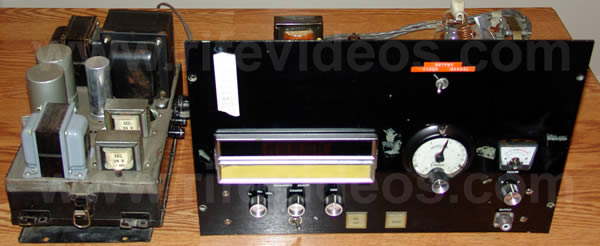
The photo below shows the two chassis that were connected by wires with their covers taken off. This instrument was a mix of both tube technology and modern solid-state components.
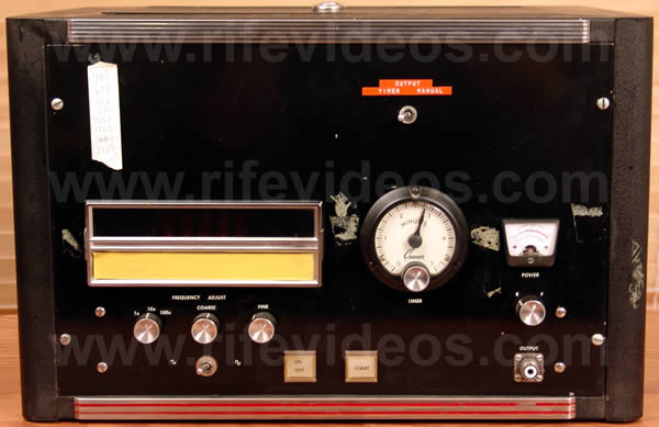
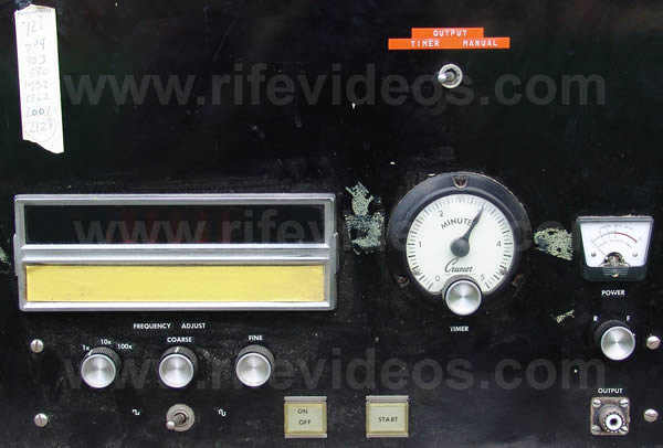
In the next photo, shown below, you can see that the instrument could output both sine and square wave audio frequencies. The frequency range of the audio oscillator went from 20 Hertz to 20,000 Hertz over three bands. John Marsh initially wanted it to have a frequency range from 0 to 100,000 Hertz. It had coarse and fine adjustments for the audio frequencies. Above those knobs, we see the digital readout window of the frequencies. John Marsh put in a modern solid-state audio oscillator with a digital readout. To the right of the digital readout, we see a timer with a range of up to 5 minutes.
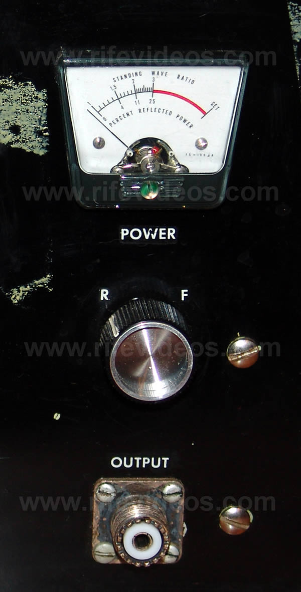
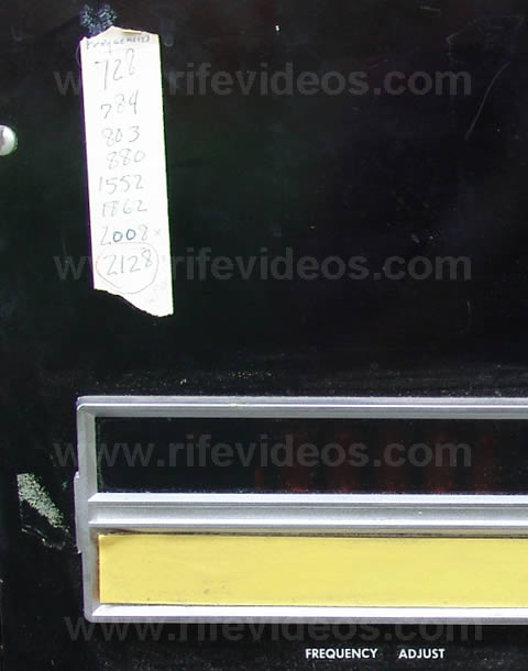
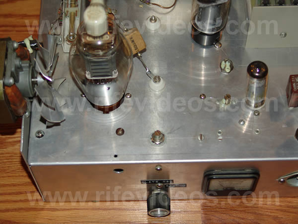
To the right of that timer, shown in the photo below, we see the power meter which is written on it “Standing wave ratio” and “Percent reflected power”. The knob below the meter was for adjusting the standing wave ratio. Below the knob is where the ray tube was connected. John Marsh used the CB antenna style connection instead of the banana jack method used in the original 1953 AZ-58.
In the next photo, shown below, you can still see an up-close view of the John Marsh's masking tape with the 1950’s frequencies written on it.
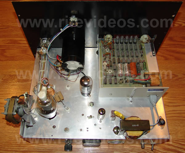
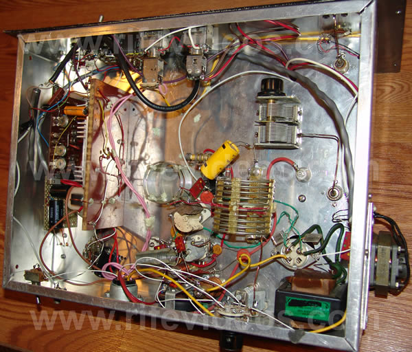
The next photo, shown below, is a top view of the chassis with the case removed. You can clearly see that John Marsh used a mix of old tube technology and solid-state electronics.
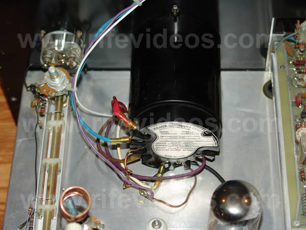
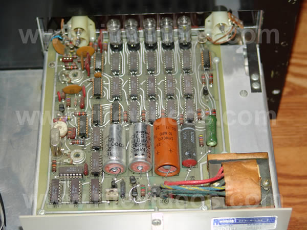
The next four photos, shown below, are close up photos of the top of the chassis. The first photo is the built-in timer. The second photo is the solid-state audio oscillator. The third photo shows the 811a main power output vacuum tube. The fourth shows the transformer that powers the audio oscillator board.
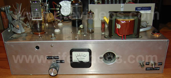
The next photo, shown below, is a back view of the instrument. The meter is a D.C. milliamp meter. The socket to the right of the meter is for connecting the smaller box that has the power transformers.
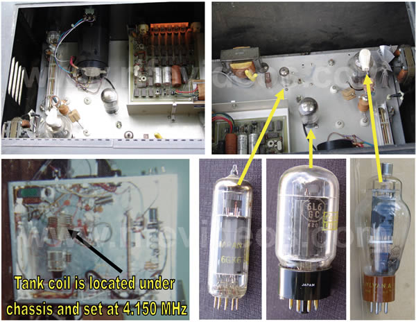
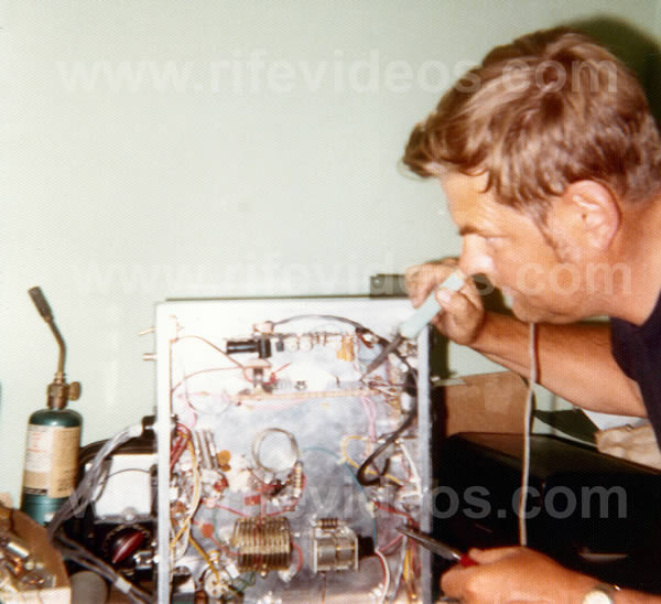
In the next four photos, shown below, give you an understanding of the various components. The first photo labeled #1 is looking at the inside front of the instrument and shows the audio oscillator. To the left of the audio oscillator is the five-minute timer. Photo #2 is looking at the back of the instrument and shows the three vacuum tubes. The three photos of vacuum tubes labeled #4, #5 and #6 show a clear view of the 811a, 6L6GC and 6GK6 vacuum tubes and their placement into the chassis. Photo #3 is one of John Marsh's original 1970 photos which shows the underside of the chassis where you can see the RF tank coil that was fixed at 4.150 MHz (4,150,000 Hertz).
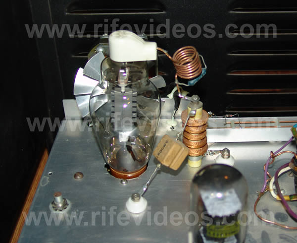
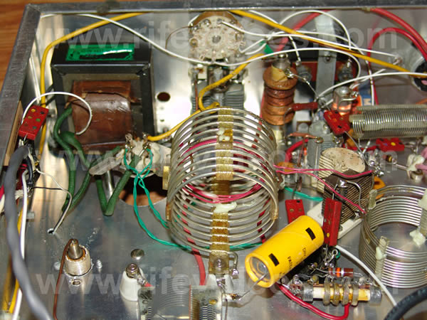
The next photo below shows a side view of the 811a tube. You can also see the RF choke right in front of the 811a tube with a small coil on top of it. This coil helped eliminate any parasitic oscillations.
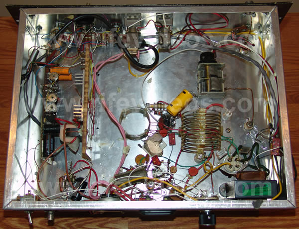
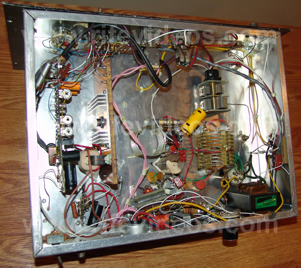
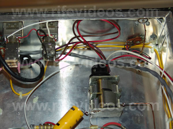
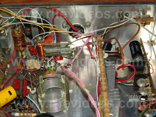
Three of the next four photos, shown below, are the new photos that were taken of the underside of the chassis. The first photo was one of the three pictures we have of the underside of the chassis. This photo was not very detailed and was taken back in 1971 when the instrument was built. In the second photo (new clearer photos) the larger coil is the RF tank coil which was set to 4.150 MHz. The variable capacitor which has the black knob was used to tune the carrier frequency to 4.150 MHz. The third and fourth photos are taken at different angles so that you can see the components.
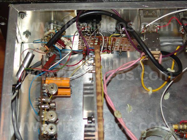
The next four photos, shown below, are up-close photos of the underside of the chassis showing the various components used to build this instrument.
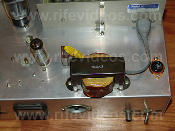
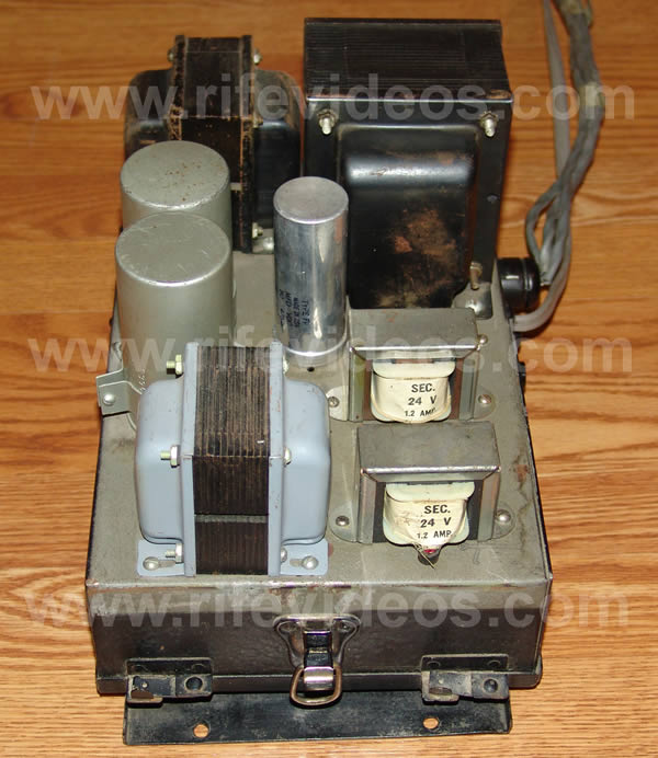
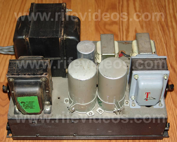
The next two photos, shown below are of the inside of the small case. It contained almost all the transformers. The standard Beam Ray Rife Machine had two shelves in one case for components. The AZ-58 combined everything into one case but for some reason, John Marsh used two cases to hold the components.
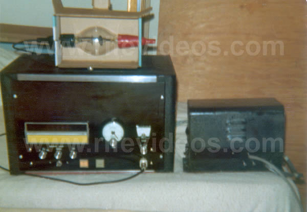
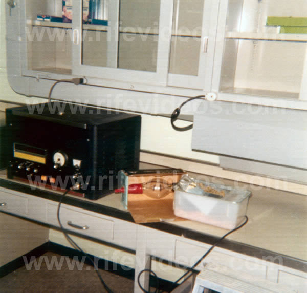
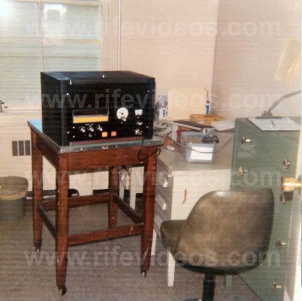
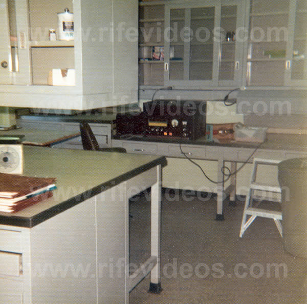
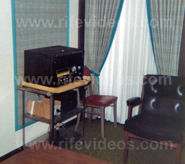
The next five photos, shown below, are of this instrument. The first four are photos of the instrument being used in a doctor's office back in 1972. The last photo is this instrument at John Marsh's home.
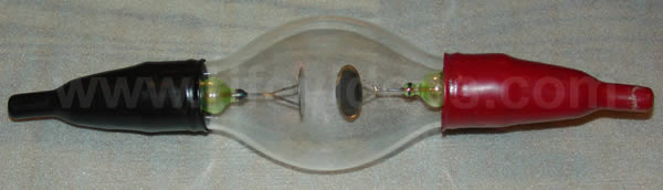
The photo below is the ray tube that was used with this instrument. The ray tube still worked when we tested it.
John Marsh's instrument, like the AZ-58, was a more modern replica version of the original Beam Ray Clinical Rife Machine. The carrier frequency that John Marsh chose to use with this instrument again clearly shows he did not understand the importance of the RF carrier frequency. He changed it from the 1953 AZ-58’s 4.68 MHz to 4.150 MHz. The 4.150 MHz RF carrier frequency is probably one of the worst carrier frequencies he could have chosen using the AZ-58 low audio frequencies for the sideband method. In fact, it would not be a good carrier for the higher audio frequencies either. We will explain again how to determine the best RF carrier frequencies to use in an instrument.
The method Philip Hoyland used to determine the best RF carrier frequency to use was by doing multiples of the BY (Sarcoma 1,529,520 Hertz) and the BX (Carcinoma 1,607,450 Hertz) frequencies. Logically, multiples of these frequencies are the best RF carrier frequencies to use because they were Dr. Rife's highest M.O.R. frequencies that he found. If you multiply the BY frequency by two you get 3,059,040 Hertz and if you multiply the BX frequency by two you get 3,214,900. So an RF carrier frequency in the 3,100,000 to 3,300,000 Hertz range would work well. Philip Hoyland used 3,300,000 Hertz. The next best range would be to multiply these two frequencies by a factor of three. The BY multiplied by three gives you 4,588,560 Hertz and the BX multiplied by three gives you 4,822,350 Hertz. So a carrier frequency in the 4,600,000 to 4,700,000 Hertz range would be the next best RF carrier frequency to use in an instrument. So you can see by the math that 4,150,000 Hertz would not be a good carrier frequency to use if you were going to use the sideband method that Philip Hoyland used when building the Rife Ray #5 or Beam Ray Clinical instrument. The RF carrier frequency should always be determined by multiples of the highest frequencies that Dr. Rife found for the various organisms. The 1953 AZ-58 had an RF carrier frequency of 4,680,000 Hertz. This carrier frequency would have worked very well had they understood the sideband method Philip Hoyland used. Since they lowered the audio frequencies instead of recalculating them to work on the sideband method then this also again reveals that they did not understand how Philip Hoyland’s instrument really worked.
With the above understanding, it is easy to see that the only reason you would use a 4.150 MHz RF carrier frequency is if you did not care what RF carrier frequency you used. The fact that they didn't really care what RF carrier frequency they used is without question since both John Marsh and John Crane have said in several documents and on audiotapes that the audio frequencies were the M.O.R. frequencies. The whole concept of using the sideband spacing method is to choose a carrier frequency that would work the best with all of the Rife Ray #4 higher frequency harmonics. Had John Marsh really understood the significance of the RF carrier frequency he would have chosen a different one. But just like the 1953 AZ-58 they changed it and relied on the square wave audio frequency harmonics rather than the sideband spacing method used in the original Beam Ray Clinical instrument. The Aubrey Scoon Beam Ray Clinical instrument replica was working on the sideband spacing method because the audio frequencies used with it were high enough to make the number of sideband harmonics reasonably low. So far Aubrey Scoon’s instrument is the only instrument that we have seen, except for the original Beam Ray Clinical Rife Machine, which worked properly on the sideband spacing method. It is clear that the 1953 AZ-58 was not working fully on the sideband principle even though it could have. It appears that just by chance or accident some of the frequencies, like the BX frequency, worked because the RF carrier frequency was set at about 3.2 MHz by Dr. Stafford. Just the fact that they lowered the audio frequencies by a factor of 10 and then depended solely on square wave audio frequencies showed they didn’t understand Philip Hoyland’s sideband method. Had Philip Hoyland revealed how his Beam Ray Clinical Rife Machine worked a lot of confusion could have been avoided. This machine of John Marsh's could have easily been changed to work properly on the sideband method. The audio frequency range was designed to go to 20,000 Hertz. If the RF carrier frequency was changed to 3,300,000 Hertz, which would have been easy to do, then most of the original audio frequencies could have been used. The only two that would need to have been re-calculated would have been the BX and the BY frequencies. This also would have been easy to do.
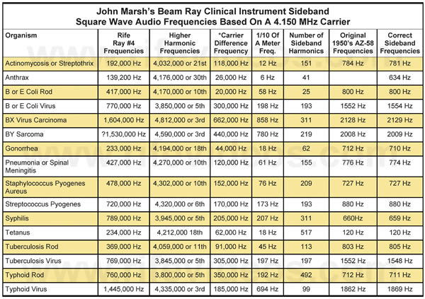
In the chart, shown below, the frequencies have been calculated for John Marsh’s instrument. You will notice that the “Original 1950's AZ-58 Frequencies” (low audio frequencies) are almost a perfect match to the “Correct Sideband Frequencies.” But before we place too much significance in this coincidence we need to keep in mind the “Number of Sideband Harmonics.” These numbers are so high that almost any low frequency can be divided into the “Carrier Difference Frequency” and come out within a few Hertz of the “Correct Sideband Frequency.” The audio frequency needs to be a great deal higher in order to make it so the sideband frequencies will work. This is due to the fact that power is lost in sidebands. We must keep in mind that the higher the audio frequency is, the lower the number of sidebands that will be created and the better they will work. So these low audio frequencies in the chart below are too low to work with an RF carrier frequency of 4.150 MHz. In fact, they would be too low to work even if they were used with a 3.30 MHz RF carrier frequency as was used in the original Beam Ray Clinical instrument. Using the higher audio frequencies like Philip Hoyland used is the method that worked in the original equipment. If the frequency you want to hit is close to the RF carrier frequency then the lower the audio frequency you can use. But if the frequency is farther away from the carrier frequency then the higher the audio frequency you will need to use in order to make it work properly. Philip Hoyland could have used even higher audio frequencies since his audio oscillator in the original Rife Ray #5 or Beam Ray Clinical instrument would go to a little over 40,000 Hertz. He could have used frequencies up in the 30,000 to 40,000 Hertz range which would have worked with even fewer sidebands. But Philip Hoyland was also trying to hide the method he was using. So Philip Hoyland balanced his frequencies in order to make sure they would work and also not reveal the method he was using. He did accomplish his goal.
If you want a higher resolution copy of this chart click here.
If you look at the “Number of Sideband Harmonics” it takes to hit the correct Rife Ray #4 “Higher Harmonic Frequencies” you will understand that this instrument could never work on the sideband spacing method using these low audio frequencies. None of the “Number of Sideband Harmonics” is less than 59 sideband steps and the highest is 75. The chance of this working would be almost zero. The best method to use with John Marsh’s instrument is the audio frequency square wave harmonic method. This is the method he used with his instrument.
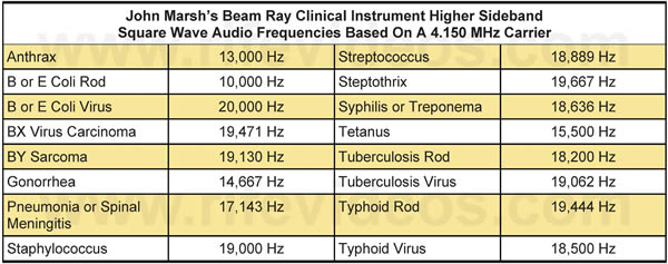
Below in this chart is a list of the higher audio frequencies, 20,000 Hertz or lower, that could be used with John Marsh’s instrument and make it work using the harmonic sideband method. Many different audio frequencies could be calculated to work. We did the highest audio frequency for each organism. The BX and the BY frequencies probably would not work since the sidebands would have to go nearly 600,000 Hertz to hit the correct frequency. For this reason, the RF carrier frequency should be changed. The best frequencies would always be the highest audio frequency you could use within the 20,000 Hertz frequency range of the instrument.
Chapter Summary: The fact that John Marsh built these Beam Ray replica Rife Machines and used different RF carrier frequencies with the same audio frequencies conclusively proves that he never understood how the instrument was really intended to work. This also shows that John Crane didn't really know how the instrument was intended to work either. John Crane was doing the same thing that John Marsh was doing. The fact that Philip Hoyland did not reveal how the Beam Ray Clinical instrument really worked has affected Rife's work in a negative way to this very day.
In chapter 16, we will look at the ray tube instrument that John Marsh built back in the 1980s when he lived in Salt Lake City, Utah.