| Home | Accessory Kit | Marsh CD Collection | Library | Contact Us |
Chapter #11
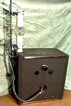
Aubrey Scoon's Rife Ray #5 or Beam
Ray replica Rife Machine Re-evaluation
1) It used a Ray Tube.
2) It used a fixed 3.30 MHz RF carrier frequency.
3) Modulated sine wave audio frequencies onto a sine wave RF carrier frequency.
4) Power usage was about 460 watts. Output to the ray tube about 50-watts.In 2009 Aubrey Scoon passed away. His web site remained up on the web until the domain name expired last year. Since his web site is no longer available and is an important part of this chapter, including this report, we have included all of his information pertaining to his machine on this web site. To fully understand this chapter we suggest that you read Aubrey's information about his Beam Ray replica instrument. Below is the link which will take you to Aubrey Scoon's original evaluation of this important instrument.
Aubrey Scoon's Beam Ray Replica Instrument
Aubrey Scoon’s 1950's Beam Ray Clinical replica Rife Machine was originally mistaken for an original 1938-1939 Rife Ray #5 or Beam Ray Clinical instrument built by Philip Hoyland and the Beam Ray Corporation. We now know that it was not an original Beam Ray instrument built by Beam Ray Corporation but it is an exact replica of that instrument. It was originally for sale on www.rife.org. John Bedini and a group of men who had worked with John Crane for one and a half years considered purchasing it. After careful examination of the information available, at that time, they concluded that this instrument was not an original Beam Ray instrument built by the original 1938-1939 Beam Ray Corporation. They concluded that it was built later, perhaps, in the 1940s by Dr. Rife’s engineer, Verne Thompson. Verne Thompson eventually replaced Philip Hoyland as Dr. Rife’s new engineer and he was building instruments during the 1940s and 1950s for doctors that wanted Dr. Rife’s machines.
The reason we are re-evaluating Aubrey Scoon's Rife Ray #5 or Beam Ray Clinical replica instrument is this instrument is the second most important instrument that we have analyzed. When it was first analyzed by Aubrey Scoon's team they did not take their original evaluation of this instrument far enough. Had they used a spectrum analyzer there is a possibility that they may have figured out how this instrument really worked, but they did not. Once we determined how the "Original Rife Ray #5 or Beam Ray Clinical" instrument worked we were able to re-evaluate Aubrey Scoon's Beam Ray replica and show that it worked on the same principles and frequencies as the original Beam Ray Rife Machine obtained from Dr. Low. All of Dr. Rife's instruments, from the first to the last, worked on the same principles and the same high RF frequencies, or higher harmonics of Dr. Rife’s original frequencies. The method of generating the frequencies may have changed but all the frequencies used in Dr. Rife's machines were based on the original frequencies he found that would eliminate, deactivate or devitalize those organisms he worked on in his laboratory.
For a better understanding of Aubrey Scoon's Beam Ray Clinical Rife Machine we need to give the history of it. Aubrey Scoon and a group of men from England purchased the above instrument believing it was an original Beam Ray Clinical instrument built by the 1938-1939 Beam Ray Corporation. The original Beam Ray Clinical instrument was known to be working on harmonics. Without really knowing it, they purchased a replica of the Beam Ray Clinical instrument. At that time no original instrument had been located. Because of this and the fact that we had no absolute concrete evidence that Dr. Rife's engineer, Philip Hoyland, built this style of audio frequency instrument it was not fully accepted as a genuine Rife instrument. Not even the later 1953 AZ-58 Beam Ray Clinical replica was accepted as a genuine instrument either.
A few years ago, before Aubrey passed away, I was communicating with him about this instrument. In the course of our communications, he told me that he believed he had used the wrong main output vacuum tube in the instrument when they worked on it. Because they believed they had used the wrong vacuum tube (812a vacuum tube) the carrier frequency had parasitic oscillations that created harmonics. He said that when they discovered this mistake they put what they believed was the proper tube (809 vacuum tube) in and most of the harmonics from the parasitic oscillations were gone. Aubrey Scoon mentions the change of this tube (809) on his web site. But they did not change the photos of the waveforms so we do not know how much the waveform really changed. This much we do know all of the photos of the waveforms on his web site are of an instrument that has parasitic oscillations. Using the wrong tube was a simple mistake that anyone could make but it led to a great deal of confusion causing many to believe, including myself, that this instrument was, an original Beam Ray Clinical instrument because of those parasitic oscillations. We believed these parasitic oscillations created the harmonics which the original Beam Ray Clinical instrument was supposed to be working on.Both Jim Berger and I separately built Aubrey Scoon’s instrument with the correct vacuum tubes (812a) and found using an oscilloscope that the RF output was clean of any parasitic oscillations. In our tests, the 812a vacuum tube produced no harmonics like those seen in Aubrey Scoon’s photos. At this time it confirmed to us that if the circuit was working correctly there would be no parasitic oscillations or harmonics from parasitic oscillations. The building of this instrument also showed that it didn't have the reported harmonics which the genuine Beam Ray Clinical instrument was supposed to have. Little did we know, at that time, that the harmonic concept we were looking for was there but we didn’t really understand how the instrument was supposed to work. This wrongly convinced both Jim Berger and me that Aubrey Scoon's instrument was not a genuine Beam Ray instrument. Nevertheless, this mistake does not change the fact that we now know that this instrument is a genuine Beam Ray machine replica.
At a later date when both the 809 and 812a vacuum tubes were tested in the circuit neither tube created the same kind of waveforms as Aubrey Scoon's machine was producing. This proved to us that the parasitic oscillations are due to some other problem in the RF circuit of his machine. It was also determined that the 812a vacuum tube was the correct tube that should be used, not the 809 vacuum tube. The 812a vacuum produces the correct carrier frequency which should be used with the audio frequencies Aubrey Scoon's instrument used.
The original Beam Ray Clinical instrument built by Beam Ray Corporation that we obtained from Dr. Low did not have any frequency list that came with it showing us what frequency band or dial settings should be used for the various microorganisms. However, Aubrey Scoon’s Beam Ray replica instrument built by Verne Thompson came with a list of frequencies that the doctor used on the various organisms. It is this list of frequencies that makes this instrument so important.
We know from the previous documents that we have read in this report that Dr. Rife had Verne Thompson rebuilding and repairing these instruments. We also read that Dr. Rife had Verne Thompson rebuilt Dr. Yale’s machine in 1940. Because Verne Thompson became Dr. Rife's engineer he would periodically repair Dr. Couche's and Dr. Tulley’s machines. We also know that Verne Thompson was making copies of Dr. Couche's Beam Ray Clinical instrument for other doctors. With this understanding, we know that Verne Thompson was the one who would have written down these audio frequencies that were used in Aubrey Scoon's Beam Ray Clinical instrument. Also with this understanding, we know that the same audio frequencies used in Aubrey Scoon's Beam Ray Clinical instrument were used in Dr. Couche's Beam Ray Clinical instrument. This information is very important. The importance of this information will become very clear as we continue to look at this instrument and the 1953 AZ-58 Beam Ray Clinical Replica instrument.
Since this paper was updated on 9/20/2010 we decided to test a 3.30 MHz RF carrier frequency believing that it could have been the correct RF carrier frequency. When Aubrey Scoon first tested the instrument with the 812a vacuum tube (not the 809 vacuum tube) he listed 3.33 MHz as the RF carrier frequency on his website. Knowing how parasitic oscillations in an RF carrier frequency could easily have shifted the carrier frequency 30,000 Hertz, it was thought that a 3.30 MHz RF carrier frequency would have been a more logical frequency to use. This assumption proved to be correct. In the summer of 2011, we obtained more of John Marsh’s documents from his nurse. In one of these documents dated November 20, 1967, John Marsh stated the following:
MARSH: “John Crane’s, a simple oscillator, which can be obtained easily for about $33.00. It produces a fuzzy band. He experimented with hooking up wires with an ordinary radio speaker and produced a different musical note for each frequency. The large instrument [Beam Ray Clinical replica instrument] is a RF frequency generator which carriers wave oscillations at 3300 kilocycles [3.3 Megahertz] on the marine band. Pre-auditory sound waves.” (John Marsh 1967 document about Dr. Robert P. Stafford).
This letter of John Marsh’s confirms that the RF carrier frequency in the original Rife Ray #5 or Beam Ray Clinical instrument, which Dr. Rife, John Crane, and John Marsh made a replica of in 1953, was set at 3.30 MHz. This also confirms that the 812a vacuum tube is the correct tube. It also confirms that the original reading done by Aubrey Scoon of the RF carrier frequency being at about 3.30 (3.33) was a correct reading. It was only slightly off due to the parasitic oscillations.
As mentioned before, Aubrey Scoon's instrument had four bands. These four bands were mentioned by Philip Hoyland in the Beam Ray Trial. He stated that they covered all the frequencies for the various organisms this instrument treated. The frequency range of each of the four bands is as follows:
Band 1: 20 Hertz to 200 Hertz.
Band 2: 200 Hertz to 2000 Hertz.
Band 3: 2000 Hertz to 20,000 Hertz.
Band 4: 20,000 Hertz to 200,000 Hertz.
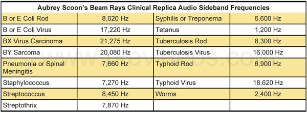
Our original Beam Ray Clinical instrument, along with Aubrey Scoon’s Beam Ray replica instrument design, predates John Crane and John Marsh and this reveals that the audio frequencies came from Philip Hoyland, not John Crane or John Marsh. This Aubrey Scoon Beam Ray replica instrument also shows a connection to the original 1938-1939 Beam Ray Clinical Rife Machine and the audio frequencies that were used in the 1953 AZ-58. This AZ-58 instrument will be discussed in greater detail later in this report. The 1953 AZ-58 Beam Ray replica instrument used almost the same frequencies as Aubrey Scoon’s instrument except Crane and Marsh divided them down by a factor of 10 times and used these lower audio frequencies in the AZ-58.Below is a chart that has the audio sideband frequencies that were used in Aubrey Scoon's Beam Ray Clinical replica instrument. It was these frequencies that John Crane and John Marsh lowered to get the audio frequencies they used in the 1953 AZ-58. We will reconcile these frequencies in this chart to Dr. Rife's original high RF frequencies that were used in the Rife Ray #3 and Rife Ray #4 Rife Machines in this section of this report. Before we do this we need to compare Aubrey Scoon's Beam Ray Clinical replica to the original Beam Ray Clinical Rife Machine which we obtained from Dr. Low.
The list of audio frequencies, shown below, of Aubrey Scoon’s Beam Ray replica sine wave audio frequencies must be used with a 3.30 MHz RF carrier frequency. Testing of this 3.30 MHz RF carrier frequency showed that this was the correct carrier frequency for this instrument. It was this testing with the 3.30 MHz RF carrier frequency in combination with the audio frequencies which produced the correct sideband frequencies that hit the Rife Ray #3 and Rife Ray #4 higher harmonic frequencies.
What we need to point out here is this IMPORTANT fact which came from the analyzing of the original Beam Ray Clinical instrument. This fact also applies to Aubrey Scoon's Beam Ray replica instrument. Neither the 3.30 MHz RF carrier frequency nor the audio frequencies will do anything by themselves. But when the 3.30 MHz RF harmonic carrier frequency and the audio frequencies are combined together they will produce many sideband frequencies. And one of these sideband frequencies will line up with the true Rife M.O.R. frequency and devitalize or render harmless the harmful microorganism. To re-emphasize this so that no one misunderstands. If you just use the audio frequencies by themselves you will get nothing. If you use the 3.30 MHz RF carrier frequency without the audio frequencies you will get nothing. The audio frequencies used in Aubrey Scoon's instrument must have the RF carrier frequency of 3.30 MHz or they are useless. This is the reason the 1953 Beam Ray Clinical instrument called the AZ-58 did not work properly. In the chart, shown below, are the audio frequencies used by Aubrey Scoon's instrument. It is these audio frequencies when combined with the 3.30 MHz RF carrier frequency that will produce Dr. Rife's higher harmonic M.O.R. frequencies. It must be understood that these audio frequencies were not meant to treat these organisms.
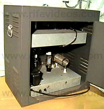
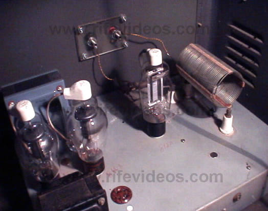
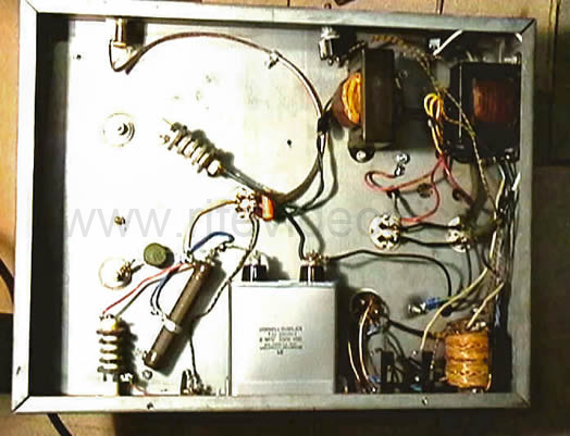
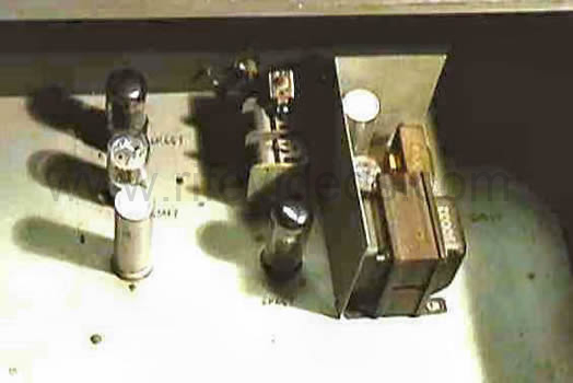
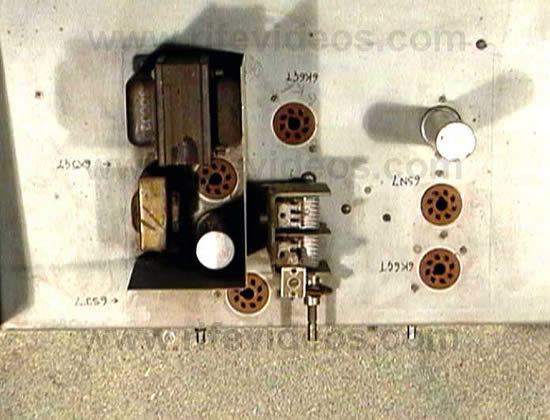
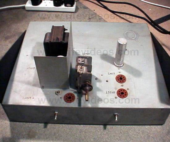
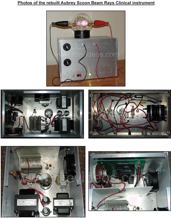
The two photos below show Aubrey Scoon's RF section. The electronic components are almost identical to our original Beam Ray Clinical instrument. It used the same 866 rectifier tubes (two used) along with the 812a vacuum tube (one used).
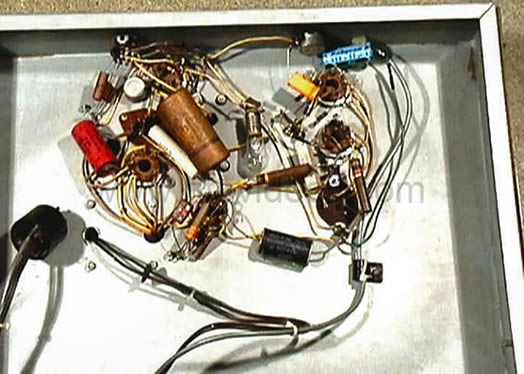
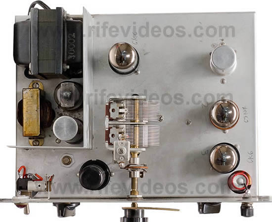
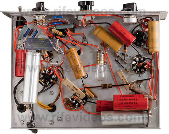
Like the original Beam Ray Clinical instrument which used a Hewlett-Packard audio oscillator, Aubrey Scoon's Beam Ray replica instrument also used a Hewlett-Packard audio oscillator design. By design, we mean that this oscillator used an incandescent light bulb in the circuit (patented by Hewlett-Packard) which stabilized the audio oscillator frequencies and waveform which it output. In the next two photos, shown below, is Aubrey Scoon's Beam Ray Rife Machine audio oscillator. In the second photo, shown below, you can see the small incandescent light bulb.
In 1938 when Beam Ray Corporation built this style of the instrument the Hewlett-Packard Wein Bridge audio oscillator was not invented yet. Since this newer Hewlett-Packard audio oscillator patent was not filed until July of 1939 and the Beam Ray Corporation was at this time in a court battle it is only logical that the original Beam Ray instrument did not use Hewlett-Packard's new design. It was invented in early 1939 and a patent was filed on July 11, 1939. The patent was granted on January 6, 1942.
In 1938 and 1939 the original 1936/1939 Rife Ray #5 Beam Ray Clinical instrument would have had an RC (resistor-capacitor) type of audio oscillator. These RC audio oscillators were known to be very unstable and it was replaced in the original Beam Ray instrument that we have with the newer Hewlett-Packard design. The audio oscillator section of the original Beam Ray Clinical instrument that we have has many extra holes in the chassis and shows that modifications were made to update this instrument to the newer Hewlett-Packard design.
Aubrey Scoon in his evaluation of his Beam Ray replica instrument believed that his instrument was an original machine built by the 1938-1939 Beam Ray Corporation. He was correct that it was an original design but he was wrong about the year it was built. John Bedini was correct in his belief that it was not an original machine built by the 1938-1939 Beam Ray Corporation. The fact that the Hewlett-Packard design patent was not issued until 1942 should have indicated to Aubrey Scoon that his instrument was built later than 1939. Rather than accept that the patent had not been filed until July of 1939 and issue until 1942 he believed that Hewlett-Packard had somehow allowed Beam Ray Corporation the right to use their design before they even filed a patent on it. Of course, this does not make any sense since they could have lost any patent rights if they did this. Just this information alone should have indicated that this machine was not an original machine built-in 1938-1939.
Aubrey Scoon's audio oscillator update
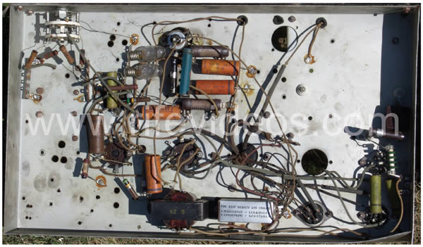
Roger Blain, who has had a great deal of interest in this technology, uncovered some very important information about the manufacture date of the audio oscillator design that was used in Aubrey Scoon's instrument. If you look at the above two photos which show both the underside and top view of the audio section of Aubrey's instrument you will notice that there are no signs of any retro-fitting of the audio oscillator to a newer design. If it had been built in 1938 or 1939 then it would have had the original (RC) resistor-capacitor design which would have been replaced. It would have also shown obvious signs of the necessary changes needed to update the old style (RC) audio oscillator to the newer Hewlett-Packard design which it has now. The next photo, shown below, shows the underside of the audio oscillator of the original 1938-1939 Beam Ray machine obtained from Dr. Low. You will notice many small holes including two larger old vacuum tube holes (empty and without any vacuum tube sockets) in its chassis. This is what we would expect to see if an instrument's audio section had been replaced with the newer more accurate Hewlett-Packard design. The lack of any modifications to the audio section of Aubrey Scoon's instrument indicates that the instrument still has the original audio oscillator it was built with. Just this fact alone puts the building of his instrument after the original Beam Ray Corporation shut down in 1939.
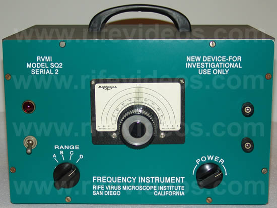
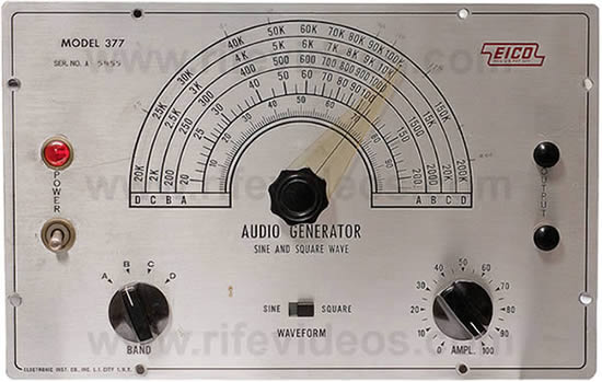
Roger Blain decided that if he could determine which design of audio oscillator was used in Aubrey Scoon's instrument then the correct dating of that instrument could be determined. In his discovery work, he found that the audio oscillator that was used in the construction of this instrument was the EICO 377. Aubrey Scoon's instrument audio oscillator frequency range and the circuit design are identical to the EICO 377 including the component values, wiring and layout. The only thing that was left out was the double pole double throw switch that allowed for switching between square and sine waves. In addition to what Roger Blain discovered another discovery has been made. The Model SQ2 pad instrument which was built and sold by John Crane and John Marsh was also the EICO 377. All they did was change the faceplate and remove the sine/square wave switch so that it would be permanently on square wave. This new information leaves no doubts as to the approximate date Aubrey Scoon's instrument was built. This new information also firmly puts its construction date in 1952 or later instead of the 1939 date Aubrey Scoon gives in his report. The first photo, shown below, is the Rife Virus Microscope Institute instrument SQ2 EICO 377. The other three photos are of the EICO 377. You will notice on the two faceplates that the screw holes along with all switches, knobs and sockets perfectly line up.
Below are three more photos. The first photo again shows the top view of the EICO 377 component layout. The second photo shows the layout of Aubrey Scoon's audio oscillator. Looking at both of these two photos you can see that the layout is identical. The third photo is a slightly different view of the second photo.
Once it was discovered that the EICO 377 was the audio oscillator that was used by Verne Thompson in the building of Aubrey Scoon's instrument we went through John Marsh's papers to see if they happened to mention the EICO 377 instrument. We found in his papers a document which shows that John Crane and John Marsh were using the EICO 377 as a contact metal pad style instrument. This new style of pad instrument used aluminum discs to come in contact with the body of the user instead of using a plasma tube. Below is a quote found in that document:
"The device consists of: 1. An audio oscillator. These are produced by various firms such as Heath Company of Benton Harbor, Mich.; Electronic Instrument Co. of Long Island City, New York; R.C.A. ; General Radio; Knight Co.; and others as well as our own which was a Hartley oscillator initially.
The model submitted herein is Model 377 EICO which is manufactured and sold by them as a commercial item." (Rife Virus Microscope Institute - EICO 377 document).
It really shouldn't be a surprise that Verne Thompson used the EICO 377 in his building of Aubrey Scoon's original Beam Ray Clinical replica design since he was also using it for their pad instrument. Since the EICO 377 was first built in 1952 this dates the building of Aubrey Scoon's instrument to 1952 or later. This is also when the 812a vacuum tube was used by Verne Thompson in the newer design called the AZ-58. The AZ-58, built-in 1953, was also a Beam Ray Clinical replica design. This explains why the correct vacuum tube for Aubrey Scoon's machine was not the 1930's 809 vacuum tube but the 1950's 812a tube.
In the 1940's and 1950's Verne Thompson was still building Beam Ray replica designs for those doctors who wanted to own an instrument. It is apparent that he was building instruments for anyone that wanted one and was not exclusive to John Crane or John Marsh since Dr. Rife and Verne Thompson did not meet John Crane until 1950. The Rife documents show that Rife, Crane and Marsh had Verne Thompson build their new machine which they called the AZ-58 in 1953. It used lower audio frequencies (original 1930's audio frequencies divided by a factor of ten times) than what the original Beam Ray Clinical design used. Even though Verne Thompson was building the AZ-58 he was still building the original 1930's design which used the higher audio frequencies. The fact that Aubrey Scoon's instrument was built in 1952, or later, proves that both designs were being built at the same time in the 1950’s. The 1953 AZ-58 was using the lower audio frequencies (from 120 Hertz to 2128 Hertz) and Aubrey Scoon's original Beam Ray replica was using the higher audio frequencies (1200 Hertz to 21275 Hertz).
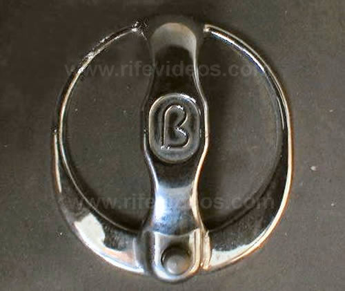
Another discovery made by Roger Blain is also important and should be mentioned here. It is in regards to the Logo emblem that was on the case of Aubrey Scoon's instrument. Aubrey believed that the "B" Logo found on his instrument must have been the original 1939-1939 Beam Ray Corporation emblem. Below in the next photo is this emblem. This was actually the Logo of the company that built the instrument case. The company was Bud Industries. This company is still in business today and are building encloses for electronic devices. Their web site is http://www.budind.com. This discovery, by Roger Blain, also indicates that Aubrey Scoon just didn't do enough investigative work or he would have also discovered that this logo was not the original 1938-1939 Beam Ray Corporations logo.
The information in the next two paragraphs should actually be in Chapter 12. But we are also including it here for those who already have a good understanding of the audio frequencies used in this type of instrument. The reason we are including this information here is some people have asked whether the low audio frequencies (120 Hertz to 2128 Hertz) used in the 1953 AZ-58 are actually the original audio frequencies used in the 1938-1939 Beam Ray machine rather than the high audio frequencies (1200 Hertz to 21275 Hertz) used in Aubrey Scoon's Beam Ray replica instrument. This is a good question and it can easily be answered with certainty. The answer is in the math which produces the correct sidebands for each organism.
Only the high audio frequencies (1200, 2400, 6600, 6900, 7660, 7270, 7870, 8300, 8450, 8020, 16000, 17220, 18620, 20080, 21275) will produce the correct sideband frequencies which will produce the higher harmonic frequencies from Dr. Rife's original frequencies. Only six of the low audio frequencies (120, 660, 727, 1862, 2008, 2127-2128 or 2127.5 Hertz as given by John Crane) used in the 1953 AZ-58 when multiplied by a factor 10 times give the exact same high frequency used in Aubrey Scoon's instrument. But the other seven (712, 784, 776, 800, 803, 880 and 1552 Hertz) when multiplied by a factor of ten times will not give the correct high audio frequency. These facts reveal which frequency list came first. Since we know that Philip Hoyland designed this Beam Ray Clinical machine and hid the method of using sideband frequencies to produce higher harmonics of Dr. Rife’s M.O.R. frequencies then only the list (Aubrey Scoon’s list) that will produce Dr. Rife’s higher harmonic frequencies could be the original list.
We will point out a few more facts. From the Beam Ray Trial, we learned that no one but Philip Hoyland understood how the instrument worked. Not even Dr. Rife, Verne Thompson, John Crane or John Marsh or anyone else understood that the RF carrier frequency had to be matched to the audio frequencies in order to produce the sideband frequencies that would hit the higher harmonic frequencies of Dr. Rife’s original frequencies. John Crane and John Marsh said many times the carrier frequency did not matter. In fact, they eventually quit using the RF carrier frequency when they built their 1950's contact pad style instrument. This clearly shows that they did not understand that the original Rife Ray #5 or Beam Ray Clinical instrument worked on harmonic sidebands. Had they understood this simple fact they never would have changed the RF carrier frequency or built their contact pad style instrument without using an RF carrier frequency. They also would not have lowered or changed any of the audio frequencies if they understood the sideband method used by Philip Hoyland. Both frequency lists would be identical except that one list would be 10 times higher than the other list. Only someone who did not understand how the audio frequencies really worked would have lowered them and then changed them. Only the list which came first would have all the correct frequencies. Again this information proves that the high audio frequency list came first. The low audio frequency list used in the 1953 AZ-58 would have come later in the 1950s because it is the frequency list when multiplied by 10 times, will only produce some of the correct sideband frequencies. Only someone such as Philip Hoyland could have made the high audio frequency list since the high audio frequencies are the only frequencies that will produce Dr. Rife’s higher M.O.R. harmonic frequencies. As we said, the answer to this question is found in the math.
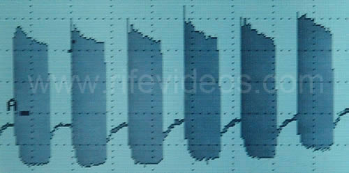
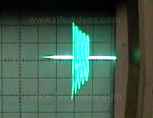
Now we will go back to the EICO 377 and Aubrey Scoon's audio oscillator. Other than the audio oscillator going to 200,000 Hertz (original Beam Ray instrument going to about 42,000 Hertz) Aubrey Scoon's instrument is a replica of the original Beam Ray Clinical instrument. With this knowledge, we know that Aubrey Scoon's instrument was a faithful reproduction of Philip Hoyland's Beam Ray Clinical instrument. Just like the original Beam Ray Clinical instrument Aubrey Scoon’s Beam Ray Clinical replica instrument used the sine wave waveform for both the RF carrier frequency and the low audio frequencies. The original machine waveform is shown in the first photo below. The second photo below shows Aubrey Scoon's instrument's modulated waveform. These two waveforms are similar. The replica that we built of Aubrey Scoon’s instrument does not have any parasitic oscillations and its waveform looks like the original Beam Ray Clinical instrument waveform shown in the first photo below.
The most important information that came with Aubrey Scoon’s instrument was the higher audio frequency list which the doctor who owned it used on his patients. Dr. Low's original Beam Ray Clinical instrument frequency list was lost to time. However, Aubrey Scoon’s frequency list was not lost so we can use it and reconcile its audio frequencies to Dr. Rife's original high RF frequencies using the sideband method that was used in this style of instrument. This statement from John Marsh shows they knew the original audio frequency range was higher than twenty five hundred hertz. Quote:
MARSH: “Were dealing with electromagnetic force field energy which is being transmitted from two different types of instruments. One instrument is a signal generator which carries two probes, one is an anode and the other one is a cathode, and they both if attached to your body and there's an infection in between the anode and cathode you become the capacitor or your part of the instrument. And so consequently the transmission of Hertz, 10 Hertz to 25,000 cycles per second. That is a very low talking range. The range I’m talking in right now which is 22,000, approximately cycles.” (John Marsh 1980's audio tape).
Since we know that Philip Hoyland tested this Clinical instrument in the laboratory he would have calculated the exact audio frequencies to hit the M.O.R.s. The Rife Ray #4 frequencies could be one-quarter of one percent off, because of the limits of the 1930's technology, if Philip Hoyland only read the frequency one time. This appears to be what happened because the frequencies read in 1935 are rounded to the nearest one-thousandth. In 1935 Philip Hoyland needed the information about the range of Dr. Rife's frequencies to build the Rife Ray #4. But in 1936 when he was building the Rife Ray #5 or Beam Ray Clinical instrument he needed more accurate frequencies for this new instrument since it was using the new sideband method. When the math was done using the high audio frequencies it showed that the frequencies were not rounded to the nearest one-thousandth, but they were more precise. It is apparent that the testing Philip Hoyland did in the laboratory in the summer of 1936 on microorganisms allowed him to get the most accurate frequency for each organism. In 1935 the Rife Ray #4 frequency given for Streptothrix was 192,000 Hertz but the frequency for the 1936 Rife Ray #5 or Beam Ray Clinical instrument was 191,803. Not only was this frequency just a little different, but all the frequencies were a little different. This indicates that Philip Hoyland took a more accurate reading of the frequencies of each organism in 1936 for use in his new instrument.
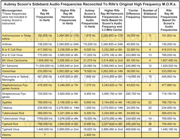
When we did the mathematical equations in order to determine if the audio frequencies from Aubrey Scoon's instrument could produce the correct M.O.R. frequencies when used with the 3.30 MHz RF carrier frequency the math had to be done in reverse order. Using the audio frequencies to determine the most accurate M.O.R.s through the sideband frequencies was the only way to figure out what the frequencies were for each organism listed. If these harmonic frequencies, when divided down, were within one-quarter of one percent of the Rife Rays #4 original M.O.R.s. then we knew that the 3.30 MHz RF carrier frequency was the correct carrier frequency. This would also prove that the sideband method was the method of producing the M.O.R.s. in the Beam Ray Clinical instrument. Doing this would also show that the two instruments worked identically the same way. Aubrey Scoon’s Beam Ray Clinical instrument with its audio frequencies would firmly prove the sideband method was the method that Philip Hoyland developed. Aubrey Scoon’s instrument would also prove that Philip Hoyland used at least two different fixed RF carrier frequencies in the instruments in order to help keep anyone from figuring out the secrets of the instruments. If the carrier frequency is different then the audio frequencies will also be different because they have to be properly matched in order to create the sidebands on the correct high RF harmonic M.O.R. frequencies.Below is a frequency comparison chart of Aubrey Scoon’s Beam Ray Clinical replica instrument. If you want a higher resolution copy of this chart, click here. In the “Rife Ray #4 Frequencies In Hertz” column are Dr. Rife's M.O.R. frequencies read by Philip Hoyland in 1935. In the “Aubrey Scoon’s Sideband Audio Frequencies In Hertz” column are the audio frequencies used to create the correct sideband frequencies to hit the harmonic Rife Ray #4 frequencies. In the “Rife Ray #4 Frequencies Based on Scoon’s Audio Frequencies” column, we see the more accurate M.O.R. frequencies that these audio frequencies produce. You will notice in the “Rife Ray #4 Frequencies In Hertz” column that the frequency for Actinomycosis or Streptothrix is 192,000 Hertz and in the “Rife Ray #4 Frequencies Based on Scoon’s Audio Frequencies” column is the frequency of 191,803 Hertz. There is only a 197 Hertz difference between these frequencies. If you compare both of these columns you will notice how closely these frequencies match up. All the frequencies which are in the column “Rife Ray #4 Frequencies Based On Scoon’s Audio Frequencies” are less than one-quarter of one percent off of the “Rife Ray #4 Frequencies In Hertz.”
Here is something that should be considered. If these 15 frequencies were lottery numbers that all had to match up the chances of them producing Dr. Rife frequencies through harmonic sidebands, with this accuracy, would be in the billions to one chances. Now keep in mind the fact that these audio frequencies range from 1200 Hertz to 21,275 Hertz and only match up with a 3.30 MHz RF carrier frequency. The distance between these sideband frequencies is significant and yet they will hit Dr. Rife’s frequencies within one-quarter of one percent to one-thirtieth of one percent. Anyone looking at this chart, shown below, can see that this could not be just a coincidence.
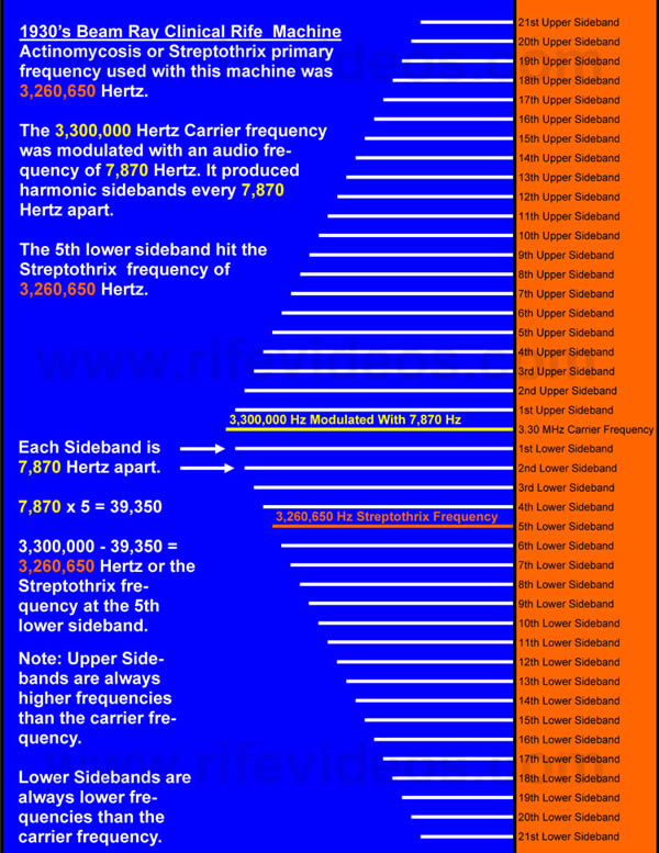
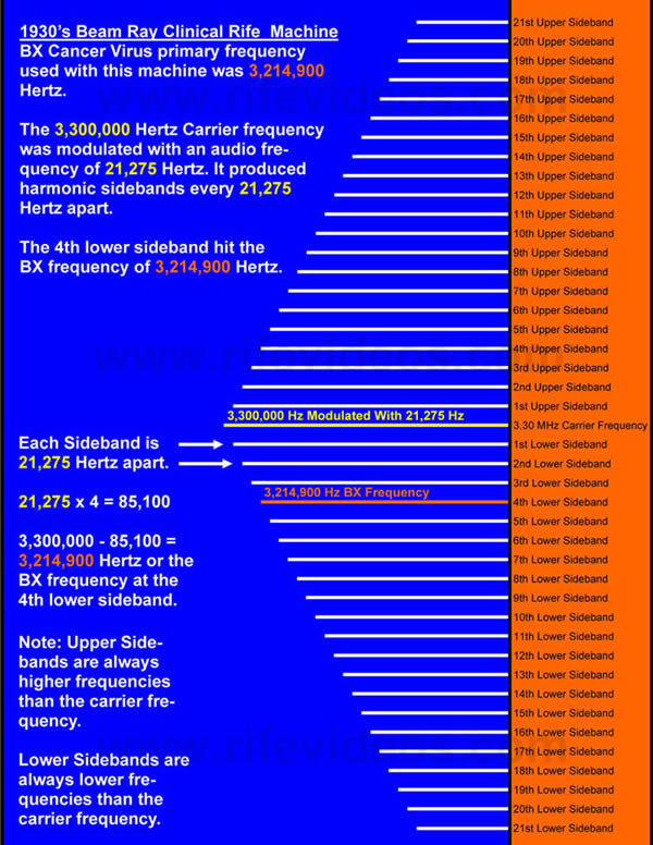
We will now give a simple description of how we reconciled these audio frequencies to Dr. Rife’s original high RF frequencies which were used in the Rife Ray #3 and Rife Ray #4 Rife Machines. The Rife Ray #4 paperwork gives us the Streptothrix frequency of 192,000 Hertz. Since we know that Philip Hoyland used the higher harmonic frequency closest to the carrier frequency in these instruments what we have to do is multiply 192,000 Hertz by 17 to get the closest frequency to the 3,300,000 Hertz. The 192,000 Hertz multiplied by 17 give us a frequency of 3,264,000 Hertz. The difference between these two frequencies is only 36,000 Hertz. This math gives us the method that Philip Hoyland used.
Now Hoyland used an audio frequency of 7,870 Hertz as the frequency to produce the proper sideband spacing in Aubrey Scoon’s instrument. If we multiply 7,870 Hertz times 5 we get the frequency of 39,350 Hertz which is the closest frequency to 36,000 Hertz. If we take 3,300,000 Hertz and minus 39,350 Hertz we get 3,260,650 Hertz which would be the higher harmonic frequency which was used by Philip Hoyland on Streptothrix. Now if we divide 3,360,650 Hertz by 17 we get the true frequency of 191,803 Hertz used by Dr. Rife on Streptothrix. Aubrey Scoon’s sideband audio frequencies now give us the most accurate frequencies for the organisms since they are not rounded to the nearest thousandth. Those frequencies are found in the above chart with the column labeled “Rife Ray #4 Frequencies Based on Scoon’s Audio Frequencies”. The math we did for the above chart shows that Aubrey Scoon’s Beam Ray Clinical Replica instrument works on the harmonic sideband method to produce the M.O.R.s.
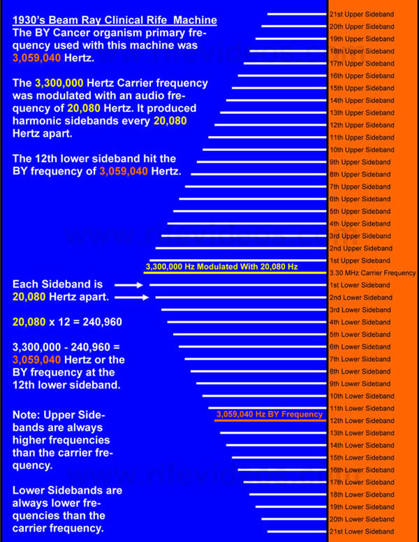
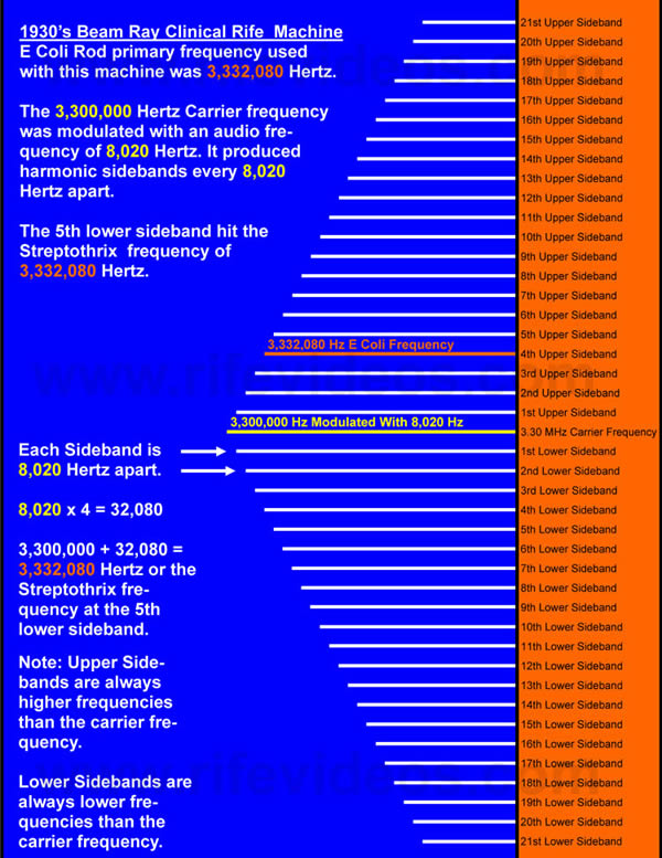
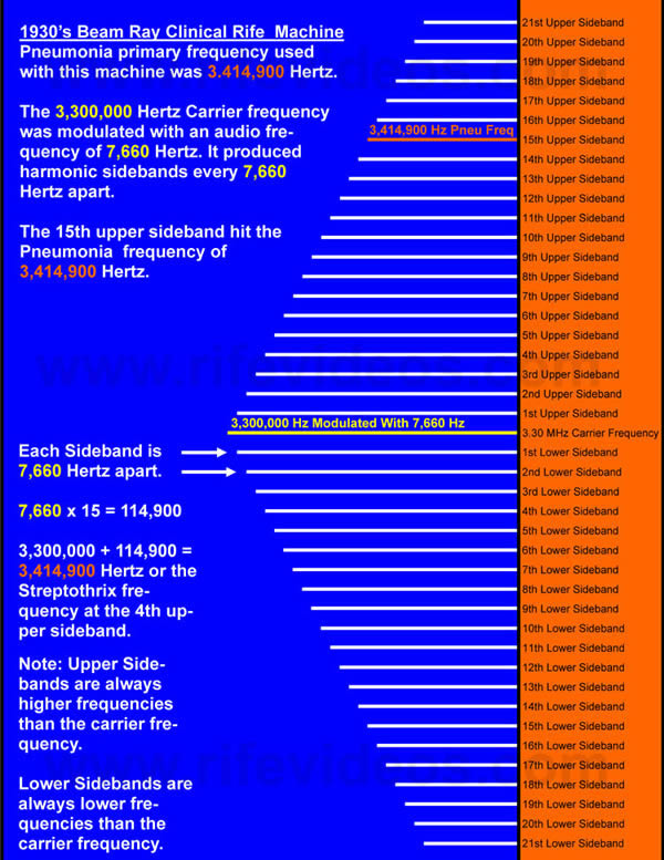
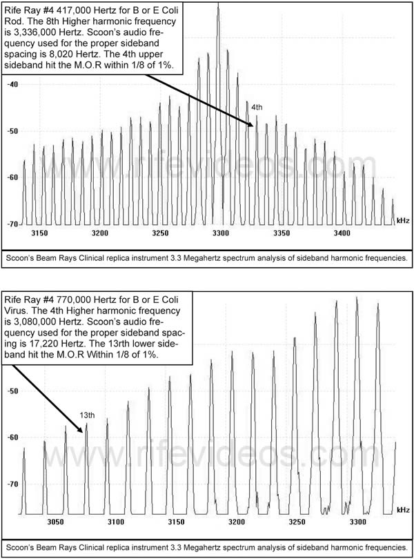
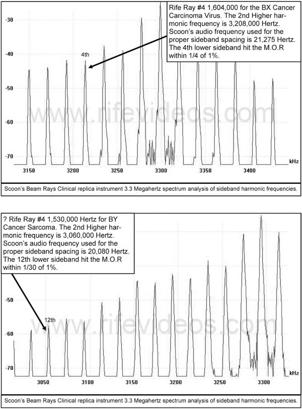
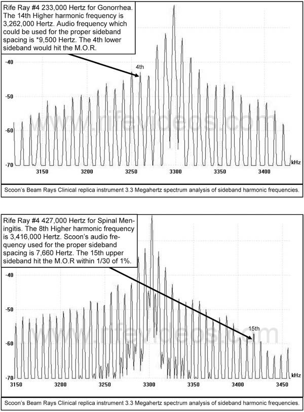
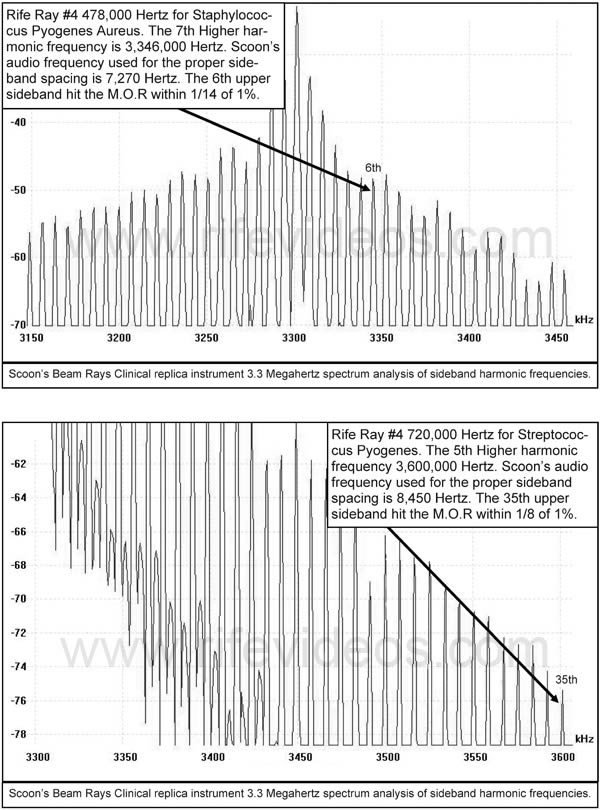
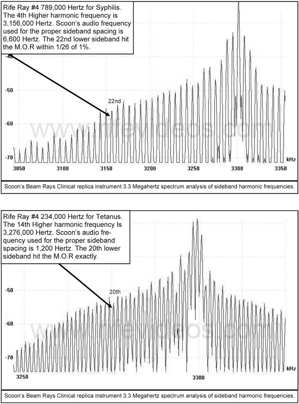
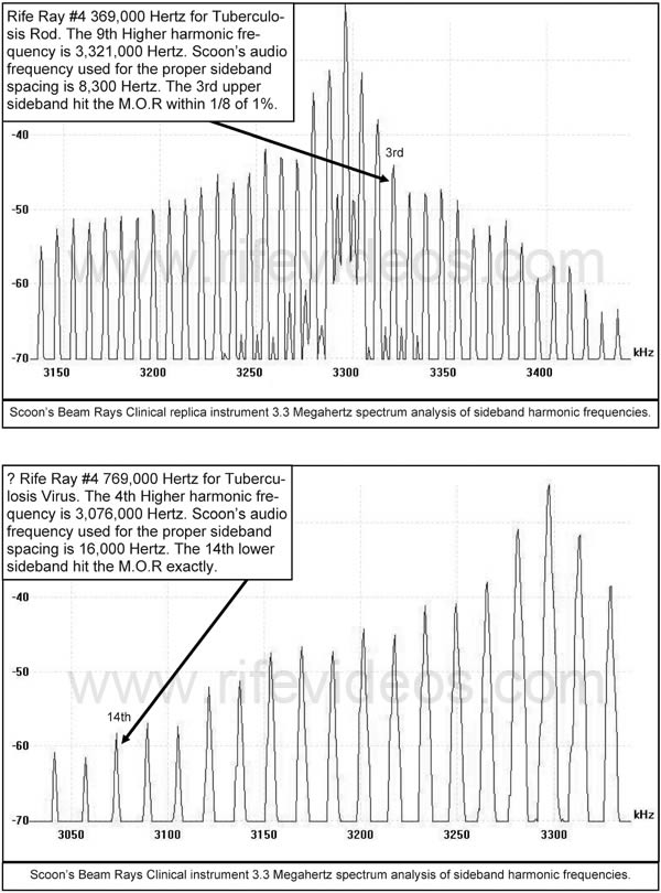
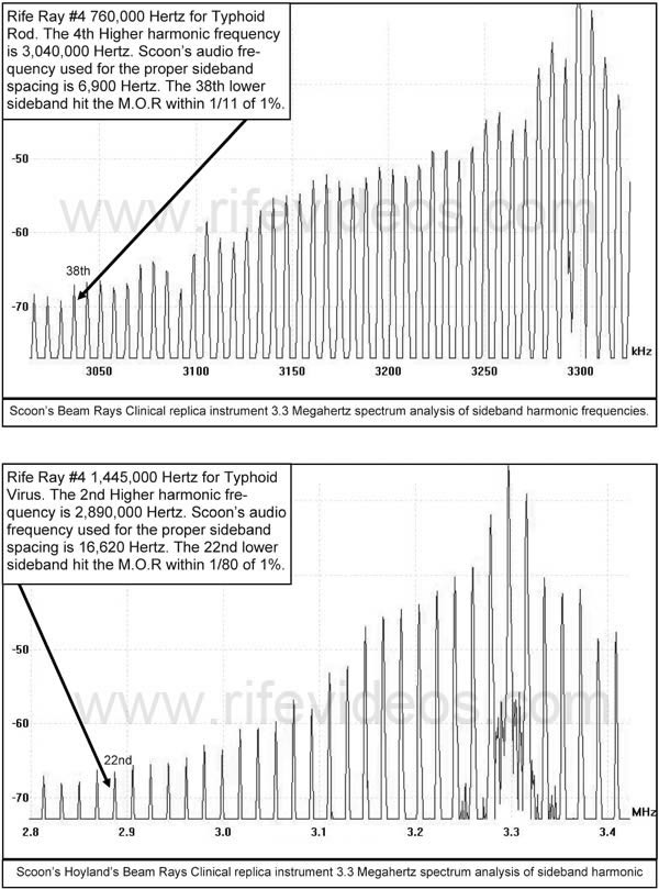
To further make this sideband method easier to understand we have made 5 charts, shown below, that clearly show how the audio frequencies used with this Rife Ray #5 or Beam Ray Clinical instrument in combination with the 3.30 MHz carrier frequency produced Dr. Rife's higher harmonic frequencies.
These sideband charts show clearly how Philip Hoyland's method worked. It wasn't until we were able to get the original Beam Ray Clinical instrument and figure out how it worked did we have the ability to determine how Aubrey Scoon's Beam Ray Clinical instrument really worked. Once we understood how these instruments really worked we could finally figure out the M.O.R. frequencies for Sarcoma, Pneumonia, and Tuberculosis. This is because some other documents that we have, give a second reference point to work with, to help us determine the correct frequency. Worms (hookworms) however, did not have a second reference point so the only way to produce the M.O.R. frequency for worms is through the sideband method using the audio frequency of 2,400 Hertz, in combined with the 3.30 MHz RF carrier frequency.
In Chapter 9 we mentioned that we would talk about the unique method that Philip Hoyland used to create the many harmonic sideband frequencies in his Beam Ray Clinical machine. The standard electronic textbooks will give you a model using a mathematic equation on how AM modulation creates sidebands. In these textbook models, which use a pure sine wave RF carrier frequency, they will show by the fourth sideband there will be no more power in the sidebands. Under normal conditions this is true but his circuit is a Low Q circuit, not a High Q circuit. This is why you will notice in this report that the spectrum analyzer graphs taken from Philip Hoyland’s instrument show that his machine produces dozens of harmonic sideband frequencies. You will also notice that these graphs do not show the dramatic power loss in the sidebands that are seen in standard AM modulation. Philip Hoyland’s unique method used a Low Q circuit and a harmonic RF sine wave carrier frequency. His modulation was more like a pulse width modulation with a 50% duty cycle.
The harmonic RF carrier frequency that Philip Hoyland used creates the many harmonic sideband frequencies, unlike the electronic textbook models. The spectrum analyzer graphs in this report clearly show that Philip Hoyland’s circuit design is very unique and produces many harmonic sidebands. To clearly state it, the graphs correctly show that the power is more evenly distributed throughout the sidebands. This means the primary RF carrier frequency does not have almost all the power in it as the electronic textbook models show. Since the power is more evenly distributed throughout the sidebands the primary RF carrier frequency may only have from a few watts to several watts of power in it and the harmonic sidebands will have the rest of the power distributed throughout them. This also means the sidebands are more powerful in this design due to the harmonic RF carrier frequency and the 50% duty cycle it naturally creates with the old vacuum tube technology. Had Philip Hoyland been able to use an even lower duty cycle the power in the sidebands would have been distributed even more evenly than with a 50% duty cycle. It must be kept in mind that the power in the primary RF carrier frequency and the sidebands depend on the power of the machine and the number of harmonic sidebands created by the audio frequency used. Philip Hoyland's Rife Ray #5 or Beam Ray Clinical instrument output about 50 watts from the ray tube. Some people question the ability of the lower power in the primary RF carrier frequency and the increased power in the sidebands to devitalize the microorganisms. But the power of this machine must have been sufficient because the tests done by Philip Hoyland, Dr. Rife and Dr. Milbank Johnson confirmed its effectiveness.
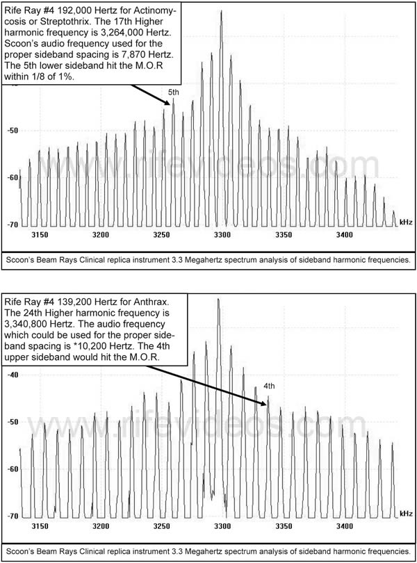
Even though we have shown the 5 charts above we have also included, below, the spectrum analyzer graphs showing the sideband frequencies for each organism using Aubrey Scoon’s Beam Ray replica instrument audio frequencies with his 3.30 MHz RF carrier frequency. These spectrum analyzer graphs also include Anthrax and Gonorrhea which was not included with Aubrey Scoon's audio frequency list.
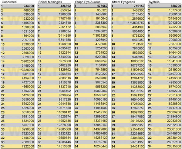
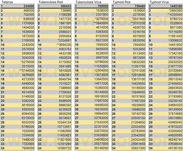
When Philip Hoyland developed this new type of Beam Ray Clinical instrument we now know that he did not use Dr. Rife’s primary original M.O.R. frequencies. We now know that he used harmonic frequencies based on Dr. Rife’s primary M.O.R. frequencies. Philip Hoyland, while working in Dr. Rife’s lab on the Beam Ray Clinical instrument apparently discovered that EVERY higher harmonic of Dr. Rife’s original frequencies could be used as a M.O.R. frequency. Dr. Rife said that he believed that many of his frequencies were sub-harmonics of a true higher frequency. But, he probably did not know that all his frequencies were sub-harmonics of higher frequencies.
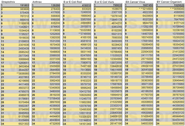
With the understanding and knowledge that every higher harmonic of Dr. Rife's frequencies could be used as an M.O.R. Philip Hoyland built the Beam Ray Clinical instruments and used these higher harmonic frequencies in these machines. In the next three charts, shown below, you will see Dr. Rife’s primary frequencies and the many harmonic frequencies that can be used. The first frequency listed under each organism is Dr. Rife’s primary frequency for that organism. The frequencies with the single asterisk* were used as the primary frequencies in Aubrey Scoon's Beam Ray Clinical instrument that used the 3.30 MHz RF fixed carrier frequency. The frequencies with the double asterisk** were used as the primary frequencies in the Original Beam Ray Clinical instrument which used a 3.80 MHz RF fixed carrier frequency. Some of the same frequencies were used in both machines and those have both the single and double asterisks.
Because of the discoveries of Dr. Rife and Philip Hoyland's use of harmonic frequencies we now know that every frequency shown in these three charts, up to the 20th harmonic, could be used as a primary frequency M.O.R. for these microorganisms. Those who have a frequency generator that can output these frequencies may want to use these frequencies. Please keep in mind that Philip Hoyland used the frequencies as high as the 20th harmonic, on some organisms, in his Beam Ray Clinical instruments so you should also be able to do the same thing. With this understanding, it is reasonable to assume that harmonics higher than this could also be used. How high harmonics can be used is not known. People will just have to test them themselves. If you want a higher resolution copy of these three charts click on, Chart 1, Chart 2, Chart 3.
The next photos, shown below, are of the Aubrey Scoon instrument that we built. The audio amplifier is on the PC board which you can see in some of the photos. This made it so we can use a modern audio oscillator to input the audio frequencies into the instrument.
Below is the schematic of this 1950's instrument. If you want a higher resolution copy of this schematic click here. The 866 vacuum tubes have been replaced with solid-state rectifiers. Also, the old vacuum tube audio oscillator was not included in the case. It is easier and more accurate to use Aubrey Scoon’s booster amplifier and a modern function generator to produce the audio frequencies that were used in this instrument. The layout of the electronic parts of this instrument is also very important because of the inherent interference problems that come with RF oscillators. Again anyone wanting to build this instrument should have a good understanding of old tube technology. Some parts of this circuit use up to 2000 volts DC with substantial current and can easily kill anyone who is not familiar with this kind of current or voltage. We take no responsibility for anyone who builds this instrument. We recommend that you have professional help.
Chapter Summary:We now know that Aubrey Scoon's instrument is a copy of Dr. Couches’ original Rife Ray #5 or Beam Ray Clinical instrument which Dr. Couche purchased from the original 1938-1939 Beam Ray Corporation. Aubrey Scoon's instrument was built by Dr. Rife's engineer, Verne Thompson, sometime in 1952 or later. Dr. Low's original Beam Ray Clinical instrument, which was built by the original Beam Ray Corporation, was the most important machine found because it made it so we now know that it was Philip Hoyland who built the audio frequency instrument that used a fixed RF carrier frequency. With this information, we were able to prove that Aubrey Scoon's instrument was a faithful replica of the original Beam Ray Clinical instrument. It came with a frequency list that the doctor who owned it used on his patients.
When it comes to the audio frequency list Aubrey Scoon's instrument is the most important Rife machine found because it gives us the original audio frequencies used in the original Beam Ray Clinical instrument. With this frequency list, we have been able to prove that Philip Hoyland used higher harmonic frequencies of Dr. Rife's original Rife Ray #3 and Rife Ray #4 frequencies in his Beam Ray Clinical instrument. This list also gives us some of Dr. Rife's frequencies which had been lost, such as the BY Cancer virus frequency. This same audio frequency list was lowered by a factor of 10 times and used in the 1953 AZ-58 which was built by Verne Thompson. With this information, we have been able to prove that these audio frequencies are not Dr. Rife's original M.O.R. frequencies and that they do not devitalize any microorganisms. These audio frequencies, when used with a 3.30 MHz RF carrier frequency, will produce harmonic sideband frequencies which will hit the higher harmonic RF M.O.R. frequencies found by Dr. Rife. Though Aubrey Scoon did not live to realize how important his instrument was we now know how important this Rife instrument really is. Dr. Low's instrument and Aubrey Scoon's instrument have revealed how Philip Hoyland's Beam Ray Clinical instrument was a harmonic instrument.
In chapter 12 we will discuss the 1953 AZ-58 and the history of that instrument in detail.